-
The red light source of the optical power meter is not charging
Recharge: Ensure the battery is fully charged before use. Use manufacturer-recommended batteries to ensure compatibility and performance. A general description is followed by explanations of how to operate the unit remotely via the serial RS232 connection. Turn on the optical power meter (OPM) using the power button. Select Wavelength: Use the wavelength selection feature to set the wavelength corresponding to the fiber optic system under test. However, should you have any questions or fi gistered users with a variety of information and services. Please allow us to serve you best by. 4 PM100D 1 General Information The PM100D Handheld Optical Power and Energy Meter is designed to measure the optical power of laser light or other monochromatic or near monochromatic light sources and the energy of pulsed light sources.
-
What is an LED light source connected to a fiber optic coupler
A fiber-coupled LED (light-emitting diode) refers to an LED device that is optically coupled to an optical fiber for the purpose of efficient light transmission. Customers can select from a wide range of LED wavelengths, spanning from Deep UV, UV, Visible, to NIR and SWIR, to meet their specific. Fiber coupled LED modules are used either for light transfer to a required location or to attach a fiber adapter that connects with a a fiber connector of choice. a battery, or a AC/DC power supply etc.
-
The function of the light guide bar light source module
Through the light diffusion structures on the incidence surface of the light guide bar and the full-reflection action of the light inside the light guide bar, the light guide bar can provide illumination with uniform brightness; and moreover, the utilization rate of. Through the light diffusion structures on the incidence surface of the light guide bar and the full-reflection action of the light inside the light guide bar, the light guide bar can provide illumination with uniform brightness; and moreover, the utilization rate of. The invention discloses a light guide bar and a light source module adopting the same. On a cross-sectional plane of the light guiding bar, there is a first line interval on the upper surface. A second line interval, a third line interval and a. Modern light guides are used for the transportation of light signals from a circuit-board-mounted LED via a particular route to a defined light-emitting surface, with minimal loss and blurring effect. They are used to illuminate areas that are too small or too hazardous to permit the installation of a light bulb.
[PDF Version]
-
How does an unequal-splitter beam splitter separate light
A beamsplitter is a common optical component that partially transmits and partially reflects an incident light beam, usually in unequal proportions. Beamsplitters are often classified according to their construction: cube or plate. 📦 For purchasing, use the RP Photonics Buyer's Guide for beam splitters. It provides an expert-curated supplier directory, buyer-focused technical background information, and structured selection criteria to support professional procurement decisions.
-

The switch s optical port light is red
It flashes green during the initialization phase, remains solid green after successful initialization, and turns red when a system fault occurs. When the Status light is red, you can use a PC super terminal to confirm whether the switch's software is running normally. PoE mode is enabled and Port LEDs function as described in Port LEDs and Modes, on page 3. The S3100 series does not have a Power indicator. S3100 SERIES SWITCHES TROUBLESHOOTING GUIDE. The status LEDs can display solid amber or flash during boot, POST, or other diagnostic tests. Power: This LED will light green after poweringthe Switch on to indicate the ready state of. Ethernet ports use LEDs to communicate link and activity status: Solid Green (Link) – Connection established and stable. Blinking Green (Activity) – Data is actively being transmitted. Amber / Orange (Solid or Blinking) – Indicates slower speed, configuration mismatch, or minor network errors.
[PDF Version]
-
Switch optical port indicator light status
Port Status LED - Indicates that the port status mode is selected when the LED is green. When selected, the port LEDs will display colors with different meanings. Understanding the lights on your network or Ethernet ports is essential for maintaining a stable and reliable network. For enterprise IT teams and engineers using Router-switch devices, these LEDs are often the first indicator of network health. This guide unpacks what Ethernet port LEDs mean, how vendors map colors and blink rates, and how to. System activity and status can be determined through the activity of the LEDs on the switch.
-
Reasons for Red Light Leakage in Optical Cables
A VFL emits a visible red laser (typically 650 nm) that travels along the fiber core and leaks out at points of excessive loss, fiber breaks, or microbends. An optical cable going bad might show symptoms like sound distortions, loose connections, visible damages, and the absence of a red indicator light. Mishandling, such as improper plugging, poor storage, and dirty connectors, can damage optical cables. This technology has revolutionized the field of telecommunications, offering significantly higher bandwidth and faster signal transmission compared to. Primarily used for Tier 1 certification and acceptance testing and the most accurate tool for measuring loss, a light source and power meter (LSPM) or Optical Loss Test Set (OLTS) can also be used for troubleshooting. By comparing the loss of the link to the requirements of the technology, you can. Visual Fault Locator (VFL) testing is one of the most fundamental inspection methods used in FTTH, ODN, and data center environments.
[PDF Version]
-
Router connected to fiber optic cable red light illuminates
Most of the time, restarting your router, checking your cables, or updating the firmware can resolve the blinking red light issue. Fortunately, diagnosing and resolving these issues doesn't have to be complicated. In this comprehensive guide, we will walk you. When your router displays a red light, it can be due to several reasons. Sometimes it may be due to a problem with your internet service provider, although you could also be experiencing this issue due to improper configuration of your router, a poorly connected cable, etc. Here you'll find out. This guide will walk you through what the LOS light means, why it blinks red and step-by-step instructions on how to resolve the issue, including resetting your router. Here are some steps you can take. We will explore common reasons behind the solid red.
-
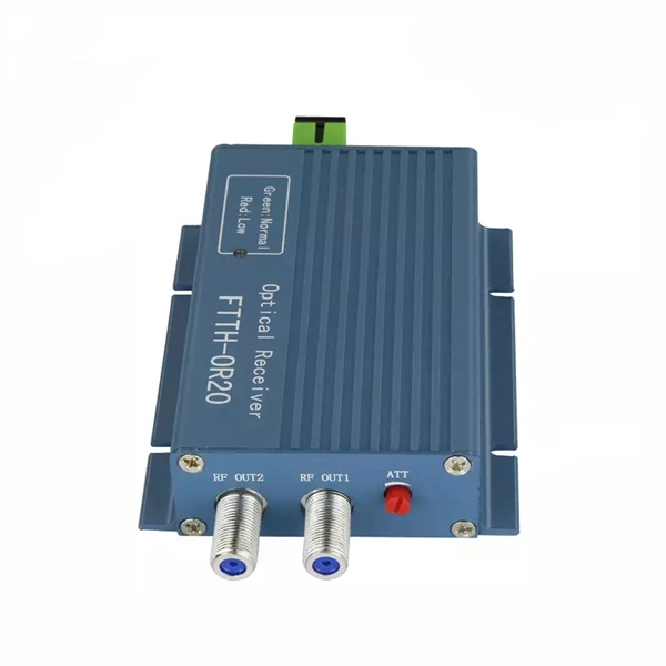
Increase the light output power of the optical module
An optical amplifier is a device which receives some input signal light and generates an output signal with higher optical power. Typically, inputs and outputs are laser beams (very rarely other types of light beams), either propagating as Gaussian beams in free space or in a fiber. At the receiver end, the optical signals are reconverted into electrical. In this guide, we will explain what optical signal strength is, how to check it on Cisco IOS using the command line, and how to troubleshoot common light level issues. Assume the. This application note gives a short introduction to optical modules and the need of an optimized power tree in them and then concentrates on the use cases and benefits of four-switch and inverting buck-boost converters inside optical modules.
-
How to read the wavelength of a source optical module
In fiber optic networks, accurately identifying the wavelength of an optical transceiver module is essential for ensuring optimal network performance and reliability. One of the most effective and widely used methods is through the pull-tab color on transceiver modules. This simple visual system. That's where an Optical Spectrum Analyzer (OSA) comes in—a powerful instrument that measures the wavelength, power, and spectral characteristics of light. Think of it as a "microscope for light," revealing details invisible to the naked eye. We all know that CWDM has a total of 12 wavelengths, with a full band range of 1270-1610nm, with each wavelength interval of 20nm. SFP+: small form-factor pluggable plus, SFP with a higher rate. Considering that some newcomers to optical modules may not understand the letters on the optical module or the. Optical power, required for measuring source power, receiver power and, when used with a test source, loss or attenuation, is the most important parameter and is required for almost every fiber optic test.
[PDF Version]
-

How do fiberglass hard tails emit light
A comet tail is a projection of material from a that often becomes visible when illuminated by the, while the comet passes through the inner. As a comet approaches the Sun, causes the within the comet to and stream out of the, carrying dust away with them. Blown by the, these materials typically form two separate tails that extend outwards from th.
-

The beam splitter has light but the main fiber has no light
A fiber-optic splitter, also known as a, is based on a of an integrated waveguide power distribution device, similar to a The system uses an optical signal coupled to the branch distribution. The splitter is one of the most important in the link. It is an optical fiber tandem device with many input and output terminals, especially applicable to a passive optical network (,,,.