-
10kV Busbar Voltage Testing Standard
IEC 61439 is a standard developed by the International Electrotechnical Commission (IEC) that covers design verification for low-voltage electrical products and assemblies. The IEC 61439. 7 cycles of 24 h each to salt mist test according to IEC 60068-2-11; (Test Ka: Salt mist), at a temperature of (35 ± 2) °C. The test shall be carried out according to IEC 60068-2-2 Test Bb, at a temperature of 70 °C, with natural air circulation, for a duration of 168 h (7 days) and with a recovery. ULTRUS™ helps companies work smarter and win more with powerful software to manage regulatory, supply chain and sustainability challenges. Consistent performance benchmarking testing capabilities for professional PC users. Award-winning software and advisory services for ESG management and. The purpose of this method is to verify the functionalities of a Metal Enclosed Busb ar. How do you check and maintain busbars? What are the faults of busbar? What is bus bar in DB? For complete safety instructions and precautions, always refer to the test equipment instruction manual.
[PDF Version]
-

Can a 10kV enclosed busbar be installed outdoors
The cable bus system described is to be suitable for indoor or outdoor installations with nominal current ratings operating in ambient temperatures to 40°C. %Optional standards for higher ambient temperatures are also availableAre you aware that improper installation of busbars can lead to costly and dangerous electrical failures? This article details the comprehensive standards for installing and inspecting busbars, including support brackets, insulators, and bus duct systems. NSPB is one of those to supply the electrical energy with greater reliability and efficiency than power cables from transformers to switchgear assemblies in 40 te for enclosures are mild steel and stainless steel.
-
The 10kV busbar has been changed from maintenance to operation
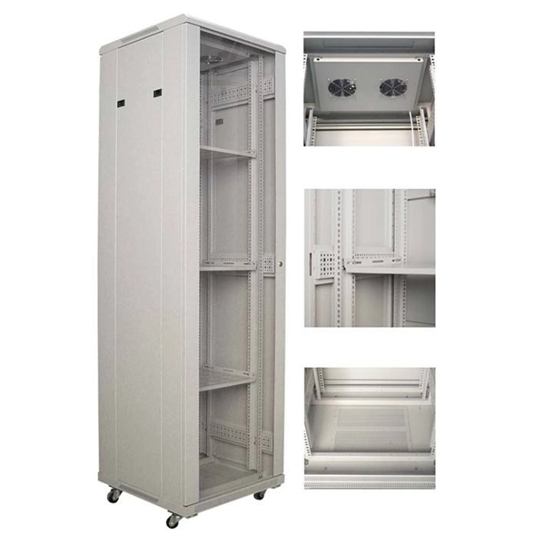
There are many standards on the subject pertaining to different voltage levels of switchgear, which normally defines four separate aspects of maintenance, with each new stage based on the preceding one, 1. Inspection, 2. Servicing, 3. Examination and 4. Overhaul. These are dealt with in detail below:Maintenance covers a wide range of activities, all of which are required to keep the switchgear in ready condition at all times to enable it perform its functions satisfactorily. The parts subjected to normal wear and agingneed to be serviced for ensuring full reliability of the operations. These parts may be mechanical components or electrical com. Safety features need to be planned before switchgear units are ordered. The requirement of locking off parts of the system (for carrying out maintenance work on the associated plant) should be finalised. Proper interlocking arrangements should be provided for this purpose. All metal-enclosed switchgears are designed so that all live conductors are.
[PDF Version]
-
Maximum allowable voltage drop value of 10kV busbar
The formula used is IMAX = (I * 100) / (100 + VD), where I is the busbar current rating and VD is the allowable voltage drop. Typical values for LV installations are given below in Figure G27. 1) These voltage-drop limits refer to normal. Instant voltage drop limits calculator: NEC and IEC compliant, auto-applies 3%/5% rules for lighting, feeders. Enter nominal voltage and optional measured drop; get pass/fail, max allowable volts, length helper instantly. Design by percent limits: compute max length, minimum size or actual drop. Voltage drop is the reduction in voltage along a bus bar due to its resistance. This standard defines the design verification, test requirements, and thermal performance of the assemblies.
-
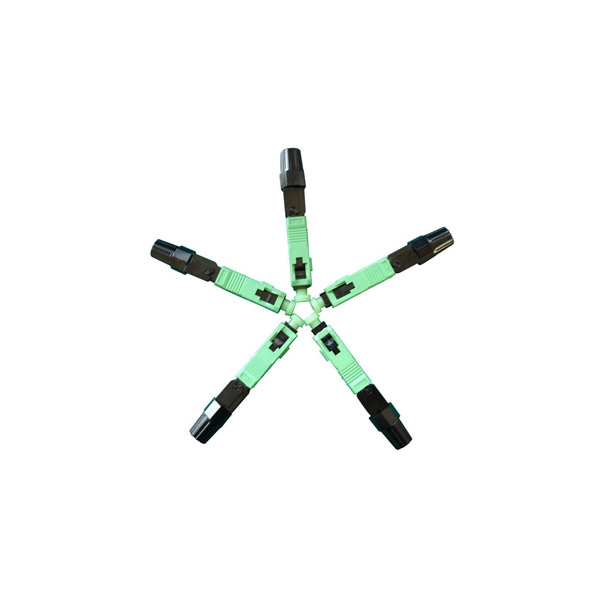
Protection level of busbar connectors
The International Electrotechnical Commission (IEC) sets out standardized testing procedures and benchmarks to ensure that busbar contact resistance remains within safe and acceptable limits. IEC standards are developed through international consensus and are used globally. The integrity of busbar joints is critical because. Busbars in power systems are the location where transmission lines, generation sources, and distribution loads converge. Because of this convergence, short circuits located on or near the busbar tend to have very high magnitude currents. The high magnitude fault currents require high-speed. Industry data shows that loose or improperly torqued busbar connections account for a significant percentage of electrical panel failures. Busbar distribution ensures these requirements are fully met. Performance criteria of. DEFINITIONS.
[PDF Version]
-
Function of the small busbar in the central power switch
The bus bar is a metal strip that distributes electrical current to the individual circuit breakers. In most assemblies you will find horizontal main bars, vertical risers, neutral and equipment-ground buses, and purpose-designed. What are Busbars, Bus Stabs, Circuit Spaces, Breaker Slots, Neutral Terminals, and Ground Terminals in an Electrical Panel or Load Center? Electric panels and load centers in residential and commercial applications have some different setting for breaker installation ad load circuit distribution. They connect directly to the main power source and are designed to handle high current loads safely. Circuit Breakers act as protective devices within the panel.
-

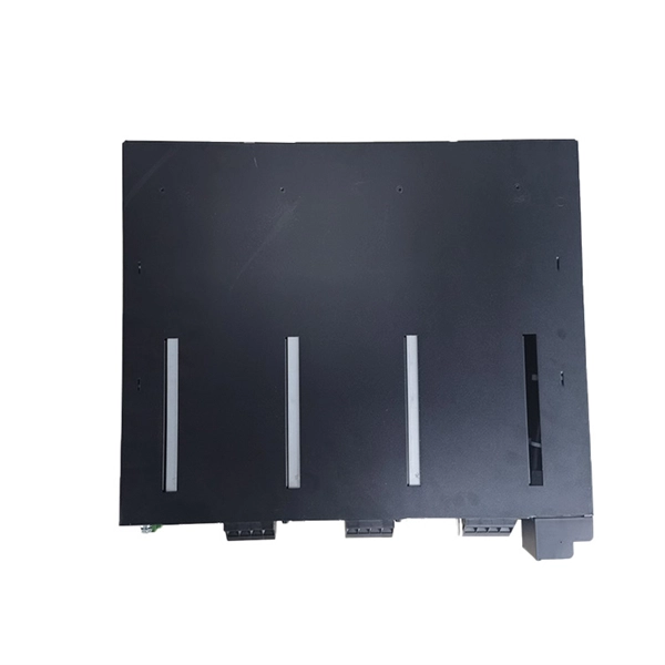
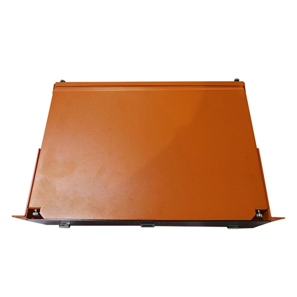
Busbar Connector Protection Box Usage
It is mainly used for insulation protection and safety protection of busbar connections in switchgear factories, power plants, and substations. In modern industrial electrical distribution systems, busbar systems serve as the backbone for power distribution, channeling electricity from main sources to various circuit protection devices and loads. The connection between molded case circuit breakers (MCCBs) and busbars represents a critical. The busbar joint protection box is made of radiation cross-linked polyolefin material. It has excellent physical, chemical and electrical properties. The high magnitude fault currents require high-speed. DEFINITIONS.
-
Standard Requirements for Busbar Connection Distance
The IEC standard for busbar clearance plays a critical role in the design and safety of electrical panels and power distribution systems. Key technical considerations include: 1. These clearances help prevent arcing, short circuits, and. Undersized busbar spacing is not a cosmetic defect. Dielectric tests, power frequency withstand for all voltages and impulse withstand for medium voltage, are specified in the standards. The design must pass these tests.