-
How to connect the traction rope for optical fiber communication cables
Use a swivel pulling eye to connect the pull rope to the cable to prevent pulling tension causing twisting forces on the cable. When the ground conditions are complex (such as rivers, trees, etc. The belt is then driven by a. In fact, there are two methods for aerial optical cables laying: one is "fixed-pulley traction method", including "manual traction method" and "mechanical traction method"; the other is "cable tray moving and releasing method". Outdoor cable may be direct buried, pulled or blown into conduit or innerduct, or installed aerially between poles.
-
Principle of Optical Fiber Communication Refraction
Refraction, or the change in the direction of light as it changes speeds passing from one material into another, is a key component in fiber-optic transmission. An optical fiber can be understood as a dielectric waveguide, which operates at optical frequencies. Following image depicts a bunch of fiber optic cables. The principles that cause an object in water to. Optical fibers are thin glass rods that use the properties of light reflection and refraction to transmit data over long distances. Sinceeach mode travels at a different velocity on the fiber, an optical bit launched into the. Fiber-optic communication is a method of transmitting data from one point to another by sending infrared light pulses through an optical fibre.
-
Budget for underground optical fiber cables for railway communication
Armored fiber optic cables designed for direct burial cost $6-14 per linear foot. Conduit systems add $2-4 per foot but allow future cable additions. These fiber cables connect and transmit real-time data to the ROC for signaling and train control, train movements, traction power substation systems, passenger. Our RDSO-approved Armoured Optical Fiber Cables are engineered for high-performance underground installations in railway signaling and telecom networks. Compliant with IRS:TC 55-2006 Rev. 2 meters (3-4 feet) deep to reduce the likelihood of accidentally being dug up. In extreme cold climates, cables may need to be buried at greater depths where there temperatures are colder and frost penetrates to. The Federal Railroad Administration (FRA) sponsored an evaluation conducted by Transportation Technology Center, Inc. regarding the opportunity and availability to use Fiber Optic Acoustic Detection (FOAD) in the North American railroad industry.
[PDF Version]
-
What are the three protections for optical fiber communication
OTN protection layers, including OCH, OMS, and OLP protection, plays a critical role in maintaining reliable connectivity in optical networks. This article delves into the various. To secure your fiber optic networks, follow the proven strategies listed below: 1. Methods of Protection Against Rodents Rodent protection methods can be categorized under five main headings: 1. Selected by the community from 35 contributions. If you have a seamless and timely record of where and how cables have been laid and.
-
Fiber optic communication optical slave
Modern fiber-optic communication systems generally include optical transmitters that convert electrical signals into optical signals, optical fiber cables to carry the signal, optical amplifiers, and optical receivers to convert the signal back into an electrical signal. The information transmitted is typically digital information generated by computers or telephone systems. Transmitters The most commo. OverviewFiber-optic communication is a form of for from one place to another by sending pulses of or through an. The light is a form of. First developed in the 1970s, fiber-optics have revolutionized the industry and have played a major role in the advent of the. Because of its advantages over electrical transmission, optical fiber.
-
Performance of ordinary optical fiber cables for communication
Fiber optic cables are essential components in modern data transmission infrastructure. They support high-speed, interference-resistant communication and are particularly effective in applications that require high bandwidth, low latency, and strong signal integrity. It traces OFC's. is this technology that provides homes and businesses with fiber-optic internet, phone and TV services. Charles Kuen Kao is known as the “father of fiber optic communications” for his discovery in the 1960s of certain physical roperties of glass, which laid the groundwork for high-speed data. Abstract—The development of optical fiber has compared to earlier copper cables.
-
Optical Ground of Fiber Optic Communication Line
OPGW (Optical Ground Wire) is a kind of cable that comprises the dual functions of grounding and fiber optic communication. It is increasingly utilized in high-voltage transmission lines as a functional element that both safeguards the power system and allows data sharing across the. An optical ground wire (also known as an OPGW or, in the IEEE standard, an optical fiber composite overhead ground wire) is a type of cable that is used in overhead power lines. Widely used in overhead transmission lines, OPGW plays a crucial role in modern smart grids, telecom integration, and utility infrastructure.
-

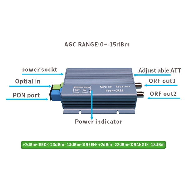
How to calculate optical attenuation in communication optical cables
Optical attenuation compares input and output power on a logarithmic scale. When powers are in linear units, the loss in decibels is: Attenuation (dB) = 10 × log10 (Pin / Pout) If the link length L is provided, the attenuation coefficient is: Coefficient (dB/km) = Attenuation (dB) / L (km) For dBm. Signal attenuation refers to the progressive loss of signal strength as it propagates through a medium—whether free space, coaxial cable, or twisted pair. Use this Optical Fiber Attenuation Calculator to calculate total signal power loss through fiber optic cables using fiber length, attenuation coefficient, connector count, and splice count. Getting this right matters in telecommunications infrastructure, data center interconnects, and submarine. Explore the attenuation formula in optical fibres, factors affecting signal loss, and an example calculation for network efficiency. You can apply this methodology to all types of optical fibers in order to estimate the maximum distance that optical systems use. There are no specific requirements for this document.
[PDF Version]