-

How to route fiber optic cables for high-voltage power lines
This technique takes a small, lightweight fiber optic cable and wraps it around or lashes it to the power line. The cable is called optical power attached cable (OPAC), and it is lashed to the power cable with a specialized tool that is pulled from the ground, such as a. Installing ADSS (All-Dielectric Self-Supporting) cables near live power lines demands precision, compliance with safety standards, and an understanding of high-voltage risks. This guide from GL FIBER breaks down the process into actionable steps, aligned with IEEE 524 and IEC 61935-1 protocols, to. Most aerial fiber optic cables are installed by lashing to a steel messenger wire strung between poles, but there is a category of cables with special high-strength jacket designs called all-dielectric self-supporting (ADSS) cables. ADSS cables are designed to withstand very high-tension loads. bles in a high voltage environment, with typical line voltages of 115 kV or more, requires the evaluation of certain critical parameters. Curr ntly, there are a limited number of industry documents that address the requirements for optical fiber cables near high voltage circuits.
[PDF Version]
-
Where to find the specifications for the incoming lines of the distribution box
This guide contains cabling dimensions for main incoming line compartments, fusible disconnect switch mains, and circuit breaker mains in Bulletin 2100 CENTERLINE® motor control centers. The 2025 Edition of the LADWP Electric Service Requirements Manual is now available on our website in PDF format. The Distribution box system diagram mainly includes the following parts: Incoming line part: Displays the incoming line source of the distribution box, which may be a single-line incoming line or multiple-line incoming lines (such as normal power supply and backup power supply), and marks the. That cable running from your main service entrance to your distribution box isn't just another wire – it's the critical link that determines how safely and efficiently power flows through your entire building.
-
Does optical fiber play a significant role in overhead power lines
The integration of fiber optics into overhead power lines has revolutionized how power grids operate, enabling greater efficiency, enhanced reliability, and improved safety. The evolution of power transmission systems has long been driven by the need for increased capacity and. For monitoring and managing networks, they use a variety of means of communications, including running fiber optic cables along the transmission and distribution towers, radio links and contracting landline and cellular communications services from telecom carriers. Utilities build fiber optic. Optical attached cable (OPAC) is a type of fibre-optic cable that is installed by being attached to a host conductor along overhead power lines. Utilities saw that, too, but to them, sending signals over glass solved a major problem: electrical interference from high-voltage transmission lines. Understanding their distinctions is essential before committing to either solution. What Are ADSS and OPGW Cables? All Dielectric.
[PDF Version]
-
Standards for Direct-Buried Optical Cable Lines
101 describes characteristics, construction and test methods of optical fibre cables for buried application. Note that Recommendation ITU-T L. However, simply hitting this depth isn't enough to guarantee your network survives. Factors like the. The Fiber Optic Association, Inc. The charter of the FOA was to promote professionalism in fiber optics through education, certification, and. Underground cables are pulled in conduit that is buried underground, usually 1-1. 2 meters (3-4 feet) deep to reduce the likelihood of accidentally being dug up. The following formulas may be used to determine general guidelines for installing Corning Optical Communications fiber optic cable; however, refer to the cable specifi simply double the minimum working bend radius.
-
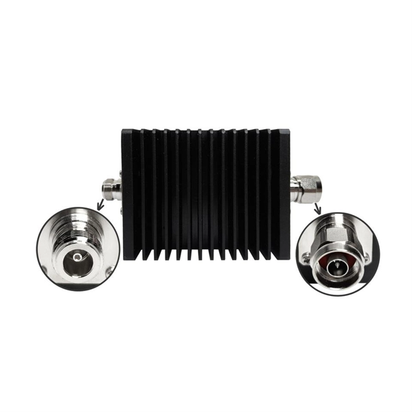
Adjacent lines in relay protection
Such protection relays are known as “distance protection relays” and only function in case of faults that occur between the location of the protection relay and the chosen reach point. Therefore, they provide discrimination for short circuits that may occur in different line . Distance elements are a workhorse of line protection. Volume IV – Substation Protection. The facilities to which this Document applies are generally comprised of the fol-lowing: In analyzing the relaying practices to meet the broad objectives set forth, consideration must. ve reliable and properly coordinated relay settings. When developing a protection philosophy, clear indication should be given for special cases where. parallel lines, the concept of Mutual Coupling will have to be considered. For three-terminal lines, the effect of app mission lines are terminated at substations, where the relays are located. It can simply be adjusted to make a unit protection arrangement when.
[PDF Version]
-
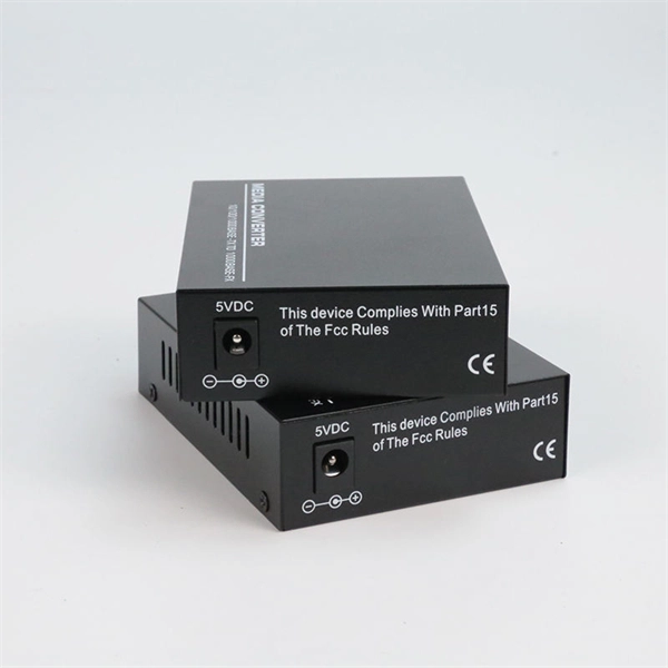
The role of feeder lines in communication towers
Telecommunication towers demand feeder cables engineered to withstand brutal environmental stressors—including temperature extremes, moisture, and chemical exposure—that can degrade performance and compromise signal continuity. Resilience is not optional; it's foundational to. Feeder lines (in red) provide communication with important nodes. A feeder line is a peripheral route or branch in a network, which connects smaller or more remote nodes with a route or branch carrying heavier traffic. The term is applicable to any system based on a hierarchical network. The quality and design of feeder cable can significantly. In the case of a telecommunications tower, these electrical currents take the form of surge currents in telecommunications and power feeders.
-
Testing Standards for Power Fiber Optic Cable Trunk Lines
FOA procedures, such as OFSTP-7 (single-mode) and OFSTP-14 (multimode), align with TIA and IEC standards. FOA standards help you with installation, testing, and troubleshooting in real-world conditions. These parameters ensure your network meets performance and compliance requirements. You need to measure how much signal is. d suppliers of electrical construction services. Existence. ANSI/TIA‑568. 3‑E “Optical Fiber Cabling and Components Standard” was developed by the TIA TR‑42. Scope: This Standard specifies performance, transmission, and test and measurement requirements for premises optical fiber cable. A practitioner-level walkthrough of the IEC 60794 framework: standard structure, mechanical and environmental test methods, type vs routine testing, common failure modes, and procurement specification guidance. Fiber optic testing of a newly installed system not only verifies that the system meets its design requirements, but also creates a performance baseline for all future testing and troubleshooting of t at system. The Contractor must utilize the correct equipment and testing techniques to gain acceptance, or the work cannot be approved.
[PDF Version]
-
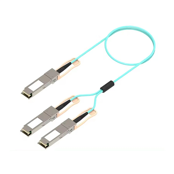
How are the lines branched on the main optical cable
Due to its bigger core, some of the light beams may travel a direct route, whereas others bounce off the cladding as shown in Figure 3. These alternate paths cause the different groups of light beams, r.
-
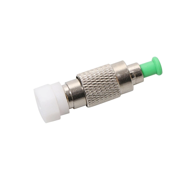
Main parameters of optical cable lines
In summary, the basic parameters of the transmission characteristics of optical fiber lines are attenuation, dispersion, and nonlinearity. These cables are used mainly for digital audio connections between devices. A fiber-optic cable, also known as an optical-fiber cable, is an assembly similar to an electrical cable but containing one or more optical fibers that are used to carry light. The optical fiber elements are typically. This guide breaks down the five core components of a fiber optic cable — from the specification package to the actual installation considerations. CHANNEL OR LINK LOSS Channel or link loss is the total path loss or attenuation between the transmitter and receiver is the sum of various loss mechanisms: scattering, microbending.