-
1-meter wide cable tray support spacing
Generally, standard trays require supports every 6 to 10 feet, while heavy-duty, long-span trays can handle distances of up to 20 feet between supports. To determine the proper spacing, consult the manufacturer's load capacity chart, which accounts for the total weight of the. The NEC requires that cable trays must be supported by members at an interval specified by the cable tray manufacturer, but not more than 5 feet for horizontal runs to support the weight of the cables and other loads. The NEC has a requirement for ladder-type cable trays. The rungs cannot be more. en completely installed, without damage either to conductors or structural system use maintain spacing or to keep cables in place when the tray is ect the minimum bend ra-dius for cables as they exit the bottom of the cable tray. Proper installation can significantly reduce electromagnetic interference, prevent fire hazards, and improve overall efficiency. This article provides an in-depth. Ladder cable tray is available in widths of 6, 9, 12, 18, 24, 30, 36, 42 and 48 inches with rung spacings of 6, 9, 12 or 18 inches. The Ladder Tray features light, rugged, tubular steel construction.
[PDF Version]
-
How far apart should the cable tray be placed with its fixed support
Support spacing for cable trays must align with the manufacturer's instructions, as outlined in NEC 392. Generally, standard trays require supports every 6 to 10 feet, while heavy-duty, long-span trays can handle distances of up to 20 feet between supports. The NEC has a requirement for ladder-type cable trays. This is a description of how to select, install, and support these metal or plastic frames, on which electrical wires are installed. You should consider it as a series of instructions that make the buildings resistant to. When installing two cable trays in parallel at the same height, the distance between them should be no less than 0. But it's also important to minimize.
-

How much distance should the cable tray support be installed
Generally, standard trays require supports every 6 to 10 feet, while heavy-duty, long-span trays can handle distances of up to 20 feet between supports. To determine the proper spacing, consult the manufacturer's load capacity chart, which accounts for the total weight of the. The NEC requires that cable trays must be supported by members at an interval specified by the cable tray manufacturer, but not more than 5 feet for horizontal runs to support the weight of the cables and other loads. The NEC has a requirement for ladder-type cable trays. This spacing is crucial for adequate maintenance access, ease of inspection, and ensuring proper airflow for effective heat dissipation. Support Methods: Common support methods include trapeze hangers, which are. This is a description of how to select, install, and support these metal or plastic frames, on which electrical wires are installed.
[PDF Version]
-
Fiber optic cable does not support 1550
Multimode fiber is designed to operate at 850 and 1300 nm, while singlemode fiber is optimized for 1310 and 1550 nm. One of the major advantages of 1550 nm transmission is compatibility with Erbium-Doped Fiber Amplifiers (EDFA). All Singlemode fibers work very similarly in either wavelength—that is, you don't need to buy fiber based on wavelength, one fiber fits all. So, IF your cable assembly is built. This article delves into why 850, 1310, and 1550 nm are standard, what less-known regimes and tradeoffs exist, and how an OEM fiber-cable manufacturer can design and test with wavelength considerations built in. Consider the balance between attenuation and dispersion when designing your network for optimal performance.
-
How to calculate the support structure for steel cable trays
Cable tray support quantity can be calculated using a simple formula: Support Quantity = Total Length ÷ Support Spacing + 1 20 ÷ 2 + 1 = 11 supports In a typical project, a 20-meter cable tray with 2-meter spacing requires 11 supports. As a key structure supporting the cable tray, the accurate calculation of the support quantity directly affects construction costs, efficiency, and safety. In complex engineering environments, the. This guide covers the critical steps, from selecting the right electrical cable tray and performing accurate cable fill calculations to managing a safe cable pull through and ensuring all bonding and grounding requirements are met. Ideal for electrical contractors and engineers. Classification of Loads Cable tray loads can be classified into the following categories: Dead Load (G): This. Correct sizing prevents sagging, overheating, and premature failure. You don't need a PhD—just a consistent method. This step‑by‑step approach helps you determine width, depth, support spacing, and allowable load with confidence.
[PDF Version]
-
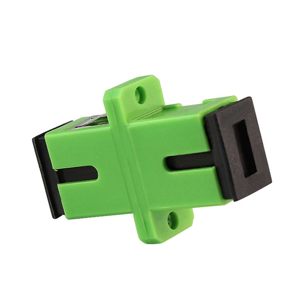
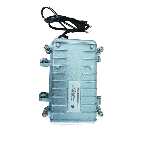
How many data rates can a single beam splitter support
Fiber signals can be split through multiple configurations including 1×2, 1×4, 1×8, 1×16, 1×32, and up to 1×64 ratios. PLC splitters are high-quality with low failure rates that offer precise equal splitting for 1260 nm to 1650 nm operating wavelengths. Ratios are. These signals are divided by optical splitters and delivered to Optical Network Terminals (ONTs) at the customer premises. A key challenge is determining how many users a single OLT port can support, which is defined by the split ratio. According to the Broadband Forum, PLC splitters are essential for achieving scalable and cost-effective GPON and XGS-PON deployment in access networks. Network Scalability Enhancement: Single fiber serves multiple users, eliminating individual line requirements.
-
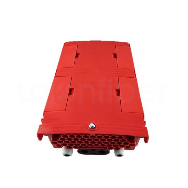
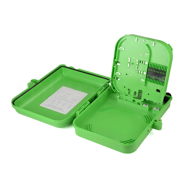
How many optical fibers can a fiber optic terminal box support at most
FTB max for mass deployment in residential units – terminates 168 fibers in a compact design. The HTB8048 Fiber Optic Terminal Box is a versatile, high-capacity termination solution for FTTx applications, offering secure fiber splicing, distribution, and cable management. The FTB product family offers modularity and ease of installation supporting multiple application options, significantly. This guide explains how to evaluate fiber termination box capacity correctly, including fiber count, port configuration, splitter accommodation, and future growth. Many buyers assume “capacity” simply means the number of adapter ports on the front panel (for example, 8 ports or 16 ports).