-
How many layers of cable tray covers are there
For cables larger than 4/0 AWG, cables are installed in a single layer (no stacking) and the sum of cable diameters must not exceed the tray width. Cable tray covers are protective enclosures that shield cables from environmental hazards while ensuring compliance with safety standards like NEC 392. 6 (requirements for cable tray installations). These essential components: Example: Stainless steel covers meet NEC 392. 10 (B) corrosion resistance. That is, it covers the top section of the cable tray. A rung spacing of 6 to 9 inches (150 to 230 mm) is preferable when the cable tray cont d for instrumentation and control applications that require. Ladder cable tray without covers provides for maximum air flow, dissipating heat produced in current carrying conductors. The fill rules differ significantly between single-conductor cables and multiconductor cables, and between ladder tray and solid-bottom tray.
[PDF Version]
-
Selection Guide for 40G Tunable Optical Modules for Broadcast Transmission Grade
In this guide, we'll explore the different types of 40G optical transceivers, compare specifications like SR4 and LR4 optics, analyze compatibility with Cisco/Juniper platforms, and provide practical purchasing guidance for enterprises looking to deploy or upgrade their. In this guide, we'll explore the different types of 40G optical transceivers, compare specifications like SR4 and LR4 optics, analyze compatibility with Cisco/Juniper platforms, and provide practical purchasing guidance for enterprises looking to deploy or upgrade their. 40G QSFP+ modules are hot-swappable, quad-lane transceivers that deliver 40 Gbps by combining four 10. 3125 Gbps electrical/optical lanes — the form factor and lane mapping are defined in the QSFP+/SFF specifications. In this guide you will learn: The real differences between the main 40G QSFP+. The 40 gigabit transceiver, particularly the 40G QSFP+ module, plays a pivotal role in modern high-speed networks, especially data centers and enterprise backbones.
[PDF Version]
-
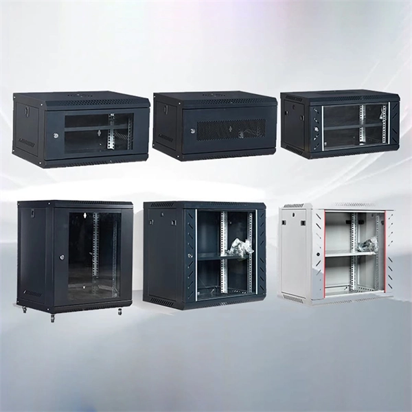
Selection Principles for Cable Tray Specifications
Cable Type and Volume: Determine the number and type of cables to be supported. Environmental Conditions: Assess indoor or outdoor usage, exposure to moisture, chemicals, or extreme temperatures. Load Capacity: Choose a tray that can handle the weight of your cables without. , is a welded wire-mesh cable management system made of high-strength steel wire. The selection of material and finish is a function of the environment in wh tant in a wide range. B. ANSI/NFPA 70 - National Electrical Code. The mechanical and electrical characteristics, tests, certifications, overall quality management, recommendations mentioned. Cable trays play a crucial role in managing and supporting electrical cables in industrial, commercial, and residential applications.
-

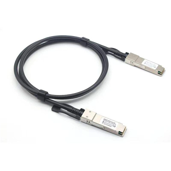
Selection Guide for AOC Active Optical Cables DML Used in Supercomputing Centers
This guide covers what AOC cables are, how they work, their advantages over copper solutions, how they compare with DAC cables, and practical selection recommendations. Need help choosing cables? Explore Ascent Optics' QSFP28 connectivity solutions or contact our. Active Optical Cables (AOCs) have become a key interconnect solution for modern high-speed networks, offering simplicity, performance, and excellent cable management. In the first. As data centers evolve to support AI, HPC, and cloud workloads, the demand for higher bandwidth and lower latency interconnects has never been greater. Selecting the wrong type for a link means either deployment failure or unnecessary cost. ***WE DO COMPATIBLE SERVICE*** 10Gtek® SFP+ Active Optical Cables are hot-swappable, low-voltage cable assemblies that connect directly into SFP+ modules at both ends.
[PDF Version]
-
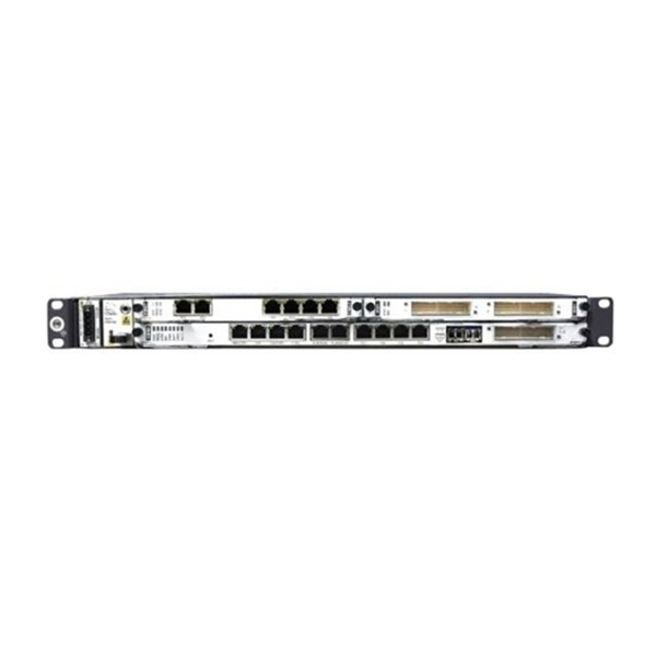
Metro-Grade OTN Router QSFP-DD Selection Guide
This guide provides a clear overview of 400G ZR QSFP-DD standards, specifications, and selection criteria for coherent pluggable optics in metro and long-haul networks. QSFP-DD ZR Coherent Optics presents a sea of change in the field of optical transportation architecture. The product supports 100Gbps transmission speeds in an. The QSFP-DD OLS is a pluggable open line system solution that can be directly hosted on a Cisco router. The Cisco® QSFP-DD Open Line System (QSFP-DD OLS) is a pluggable optical amplifier module that, together with the channel breakout options (described later), provides a simple yet powerful open. The 4. The DP01QS28-E20 and DP01QS28-E25 transceivers enhances the Routed Optical Networking solution by adding a 100G-only tuneable optic which be used across both. Quad Small Form-factor Pluggable Double Density (QSFP-DD) solution that fits into high-density switch and router client ports for optical interconnect links Powered by Greylock and Delphi DSP ASICs, and silicon photonic integrated circuits (PICs) for an optimized co-packaged design with 3D.
[PDF Version]
-
How to cover a cable tray with a right-angled cable tray
The TX bracket allows you to fabricate tee or cross combinations in the ET/ET3/ET5 tray. Simply make the appropriate cuts in the side wall of the tray you are joining a length to, bend down the side wall, and attach a TX bracket either side.Always use 2 splice plates per length of tray and SBH and CNH splice nuts and bolts to fasten them in place. EzyStrut splice bolts have a smooth head which should be installed on the inside of the tray's side wall. The SBH's smooth head is specially designed so it cannot damage any cables.The radius plate comes in a standard 2m length, and the amount of fasteners you will need to install will vary depending on the angle and size of the desired bend and tray that you are using.The ET range of trays are generally secured onto strut with hold down units. Always install them in pairs, and always secure a tray at least twice along its length.Riser links must always be installed in pairs, one on each side of the tray. The quantities that you will need to use will vary depending on the size of the riser (internal or external) that you are fabricating. If ever you need any help, EzyStrut staff know our products, and can demonstrate them.
[PDF Version]
-

Selection Guide for QSFP Active Optical Modules for Cloud Computing
This QSFP module guide delivers a technical deep dive into the most prevalent QSFP transceivers, their specs, real-world deployments, and practical buying advice. Whether you're upgrading to 100G or optimizing your 40G links, this article is tailored for network architects, engineers, and system. The Ultimate Guide to QSFP Optical Modules: 40G to 800G Interconnect Evolution In today's digital era sweeping across the globe, data centers—the core hubs of information processing—have an insatiable demand for high-speed, high-density data transmission solutions. By increasing channel density, it enables higher port utilization and seamless upgrades on existing infrastructure. As a core component of high-speed networks, QSFP-DD. As high-speed networks continue to evolve, optical transceivers like QSFP-DD, QSFP28, QSFP56, SFP56, and SFP28 have become the core components enabling scalable and efficient connectivity across data centers and telecom environments. Below is a detailed breakdown of each module series.
[PDF Version]