-

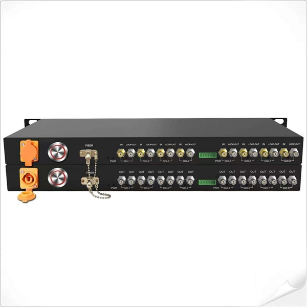
Wired Channel for Relay Protection
With the addition of a line tuner, the CCVT (used for potential input to the protective relay) can be used to couple the PLC signal to the power line. Protection systems are used to isolate faulted parts of the system, protect the electric system from instability, and minimize equipment damage. Directional distance and overcurrent schemes, interfaced with communication equipment, send and receive logic-based information between relay te minals to determine if the fault is external or internal to the. Important benefits include limiting tripping to faulted line section, high-speed simultaneous clearing for all internal line faults, preventing overtripping on external faults, and reducing transmission line and station damage. Applications of the concepts to accepted transmission line-protection schemes are also presented.
-
Several characteristics of relay protection are
To provide effective and reliable protection to the power system, a protective relay must have the following essential functional characteristics: Selective, Fast, Stable, Reliability, Sensitivity, Simple Construction and Installation Mechanism, and Cost-effective. A protective relay is an electrical switch which can automatically operate when a fault or any other abnormal conditions occur in the electrical system. It sends a signal to turn on the alarm or indicator or trip a circuit breaker to separate the faulty part from the healthy section. : 4 The first protective relays were electromagnetic devices, relying on coils operating on moving parts to provide detection of abnormal operating conditions such as. A protective relay is an intelligent electrical device designed to detect faults in power systems and initiate corrective actions such as tripping a circuit breaker. PSM – Plug Setting Multiplier (Current Setting Multiplier) What is PSM? 2).
[PDF Version]
-

Relay Protection Test Wiring Method
One approach to test the total protection system is to use primary injection techniques (see appendix H) that trigger protective relays and lockout relay, trip circuit breakers, and initiate annunciations and indications. If applicable, documentation is required detailing how verified protection segments overlap to ensure there is not a gap. The purpose of this Standard Work Practice (SWP) is to standardise and describe the method for testing of Ergon Energy protection relays for commissioning purposes. This SWP should be interpreted in conjunction with Standard for Substation Protection (V1. From a technician's perspective, master the unique skill of testing protection. When the transformer wiring type is Y/Y (Y0), the test wiring is very simple: when testing phase A, the tester IA is connected to the phase A of the high voltage side, and the tester IB is connected to the phase a of the low voltage side. After the neutral line of the high and low voltage sides is. Function: Use electronic components like transistors to perform switching. Applications: Frequency, undervoltage, and overcurrent protection.
[PDF Version]
-
Is it dangerous to repair relay protection
Doing so may result in reducing Relay performance for insulation failure, contact welding, and contact faults, and might even result in burning or other damage to the Relay itself. Do not drop the Relay or dismantle it. Refer to the Safety Precautions for individual Relays for precautions specific to each Relay. Electric shock may. A relay that is correctly set for yesterday's system may become a serious risk after a plant expansion or load change. This article breaks down the most common protection relay misconfigurations in industrial facilities, why they happen, and how they impact system reliability and operational. onding to faults, ensuring the reliability and stability of the grid. However, unauthorised changes to protection relay settings pose a significant threat to the integrity of power systems. Although failure of a protective relay system may have severe local or regional impacts, most protective relay systems are not required to operate to prove they are in working order.
[PDF Version]
-
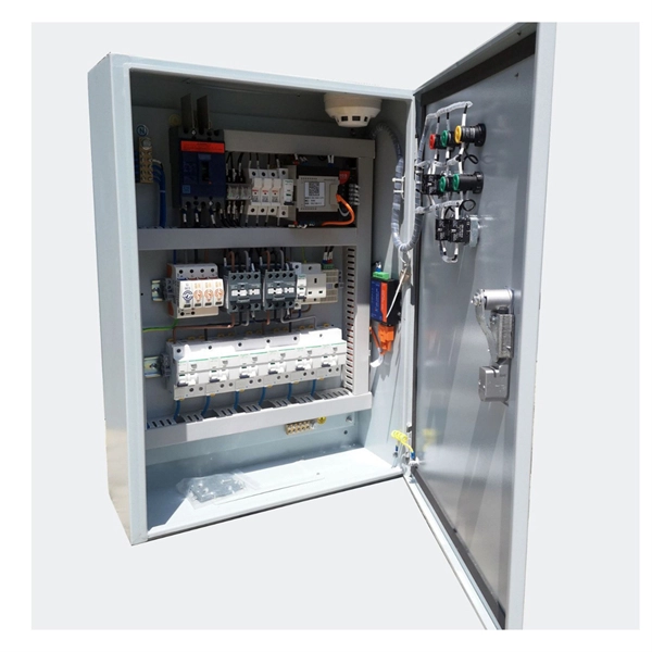
Requirements for Relay Protection Design
The IEEE standard for protection relays refers to a collection of guidelines developed by the Institute of Electrical and Electronics Engineers. This document provides recommendations, background and philosophy on relay protection that is not available in M07. They are intended to quickly identify a fault and isolate it so the balance of the system continue to run under normal conditions. For professionals working in utilities, industries, or renewable energy systems, understanding these standards is not optional—it is essential. This handbook covers the code of practice in protection circuitry including standard lead and device numbers, mode of connections at terminal strips, colour codes in multicore cables, dos and donts in execution.
-
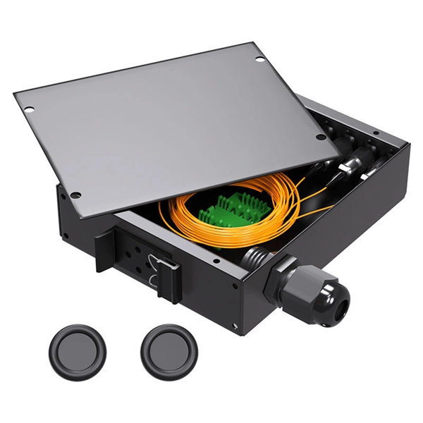
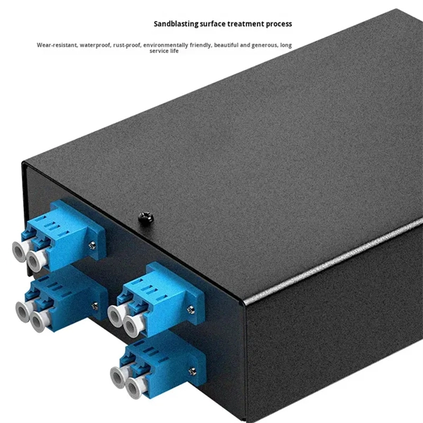
Protection Measures for Optical Cable Line Engineering
Optical cable lines lightning protection and strong current protection are achieved by avoiding, guiding or discharging them underground to prevent lightning and strong current from causing damage to the optical cable lines themselves, communication equipment and personnel. Since the lightning. The Fiber Optic Association, Inc. The conduit can be made of various materials such as PVC, HDPE, or steel. It is suitable for areas with flat terrain and small undulations. This type of fiber optic is laid in two ways: suspended under steel strand and self-supporting suspension. Local exchange carriers use fibres to carry the same service between central office switches at local levels, and sometimes as far as the neighbourhood or individual home.
-
Relay protection panel reset
Operate the mechanical reset lever or pushbutton on the lockout relay, or use the relay's HMI/SCADA interface for electronic relays. For microprocessor relays, use the front panel or remote interface to acknowledge and reset the lockout/trip condition. In this comprehensive guide, we will delve into the essential steps for resetting a relay efficiently and effectively. From troubleshooting common issues to performing the reset process step-by-step. How can I reset the Alarm or Trip on 857 Motor protection relay? There are two status indicators named "Alarm" and "Trip" on the front panel that is mapped within the Output Matrix. #relay #lockoutrelay #electrical #howtoresetrelay #86relay #mastertriprelay lockout relay function lockout relay wiring diagram lockout relay 86 protection lockout relay wiring lockout relay operation lockout relay 86. View all of Eaton's protective relays PowerPort-E can not connect to the device. The settings in a 751 shouldn't be reset because of a loss of power.
[PDF Version]