-
How much optical loss does a fiber optic cold connector typically experience
Generally, for single-mode connectors, the recommended insertion loss is below 0. Insertion loss, also known as attenuation, is the loss of optical power that occurs when light passes through a fiber optic connector. It is caused by factors such as misalignment, air gaps, and imperfections in the connector components. This article explores various connector types—such as SC, LC, FC, ST, APC, and UPC—and analyzes how their design and polishing affect IL and RL performance. Insertion Loss (IL): Measures the. Fiber loss, also called fiber optic attenuation or attenuation loss, refers to the loss of signal between input and output.
-
Fiber Optic Connector ST Inspection Standard
This standard covers the inspection of fiber optic connectors with a microscope and cleaning the connectors. Look for dirt, contamination, scratches or any other problem. adhesives for faster terminations. Single-mode and multimode connectors come with a 2-3 mm boot, a 900-micron boot, a dust cap, and a crimp ring. For optimal connectivity performance, invest in a Fiber Optic Inspection and Cleaning Kit for your installation team. The fibers shall terminate in 2. A full catalog of TIA specs is at org/ Learning More About Standards and Codes There are a number of ways of finding out more about cabling. Among these, SC (Subscriber Connector) and ST (Straight Tip) connectors stand out as widely recognized standards, conforming to the EIA/TIA 568A specification.
-

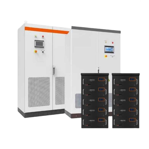
Busbar Connector Protection Box Usage
It is mainly used for insulation protection and safety protection of busbar connections in switchgear factories, power plants, and substations. In modern industrial electrical distribution systems, busbar systems serve as the backbone for power distribution, channeling electricity from main sources to various circuit protection devices and loads. The connection between molded case circuit breakers (MCCBs) and busbars represents a critical. The busbar joint protection box is made of radiation cross-linked polyolefin material. It has excellent physical, chemical and electrical properties. The high magnitude fault currents require high-speed. DEFINITIONS.
-
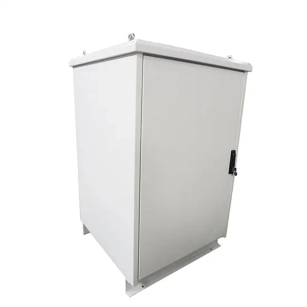
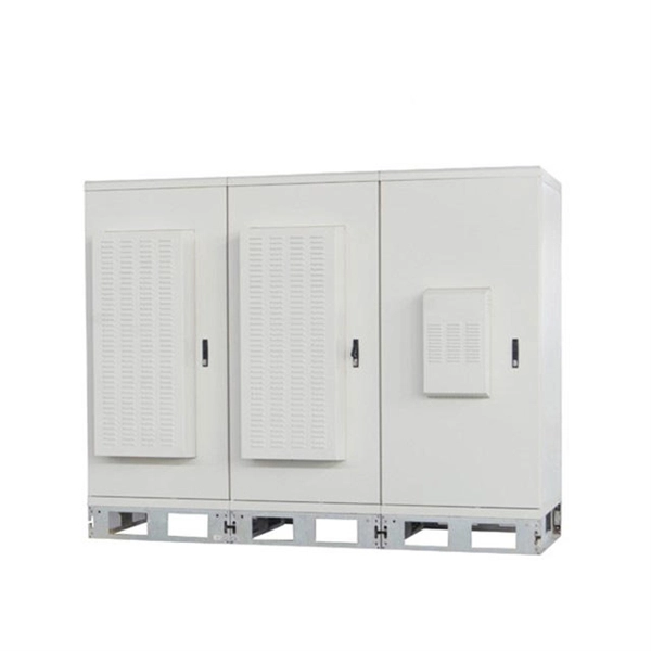
Assembly and Installation of Small Distribution Boxes
The steps to install a small distribution box include selecting a suitable location, installing the base, placing the distribution box, connecting the wires, and checking for acceptance. Warm reminder: Do not disassemble or modify without experience and professionals. It takes the incoming power and safely distributes it to different circuits throughout your building. We focus on workflow efficiency, assembly er. Select location Before. In modern electrical systems, cable distribution boxes (also known as electrical distribution boxes or distribution boxes) play a crucial role as the key hub for managing, distributing, and protecting circuits.
-

What are the labeling instructions for telecommunications fiber optic cables
TIA-606-C states that you need to label all fiber optic cables and pathways at both ends. You should place labels close to connectors—usually within 8 inches. You can also label jack, connector, and block hardware on outlets or. What's the difference between properly-labeled infrastructure and one that is not properly labeled can be seen in the final numbers. According to research conducted by industry experts that shows network failures cost businesses the equivalent of five thousand dollars per minute. For international work, IEC and ITU guidelines may also apply. These. The American National Standards Institute and Telecommunications Industry Association (ANSI/TIA) 606-B standard establishes voluntary labeling and recordkeeping requirements for telecommunications infrastructure. The goal isn't bureaucracy; it's clarity. With the right labeling system, you can trace any connection in seconds instead of hours, keep your documentation airtight, and make your infrastructure truly scalable. Get a clear overview of the.
[PDF Version]
-
Optical cable termination optical loss
Optical fiber channel insertion loss is the decrease in optical power that occurs when an active transmitter is linked to an active receiver via terminated, optical fiber cables and patch cords and may include splice points and optical couplers. This Applications Engineering Note explains how different optical fiber termination methods impact the optical performance of telecommunications systems. Optical fiber cabling systems support various communications technologies that use digital as well as analog signaling. Gigabit Ethernet (GbE). Fiber optic joints or terminations - where cables are terminated - are made two ways: 1) connectors that mate two fibers to create a temporary joint and/or connect the fiber to a piece of network gear (left) or 2) splices which create a permanent joint between the two fibers (right).
-
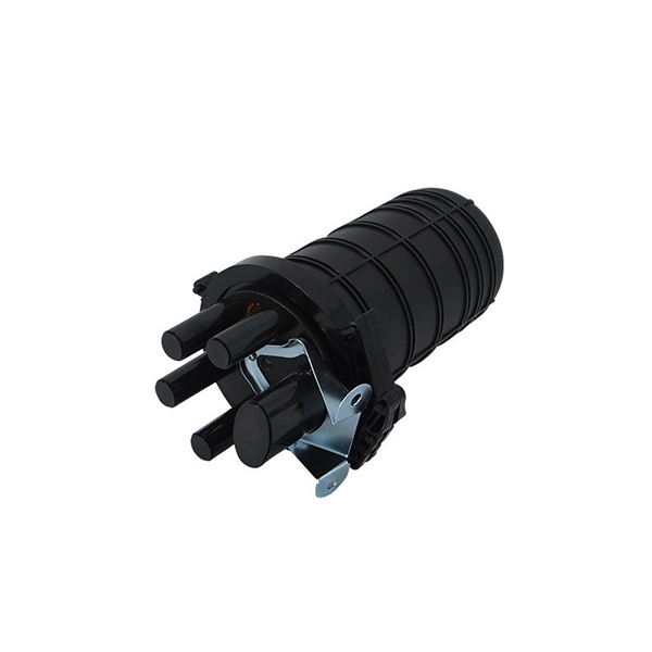
What are optical cable termination and splicing
To begin, the standard definition of splicing in optical fiber is joining two fiber optic cables together. Both techniques have their advantages and are suited for different applications, but understanding which method to use can greatly impact the network's. The critical procedure of fiber optic termination and splicing is essential in ensuring a reliable, loss-free transmission in fiber optic systems. This guide aims to provide an in-depth understanding of fiber optic termination, types of fiber optic termination, splicing methods, and the. We terminate fiber optic cable two ways - with connectors that can mate two fibers to create a temporary joint and/or connect the fiber to a piece of network gear or with splices which create a permanent joint between the two fibers. For network managers and technicians, a poor splice can lead to significant signal degradation, network downtime, and costly troubleshooting.
[PDF Version]
-
Complete Assembly of Nicaragua Primary Distribution Box
The Nicaraguan legislature is a body. It is made up of 92, 90 of whom are elected by popular vote on a basis from party lists: 20 nationally, and 70 representing the country's and autonomous regions. In addition, the who served the immediately previous presidential term is entitled to sit in the Assembly as a deputy, as is the runner-up in.
-
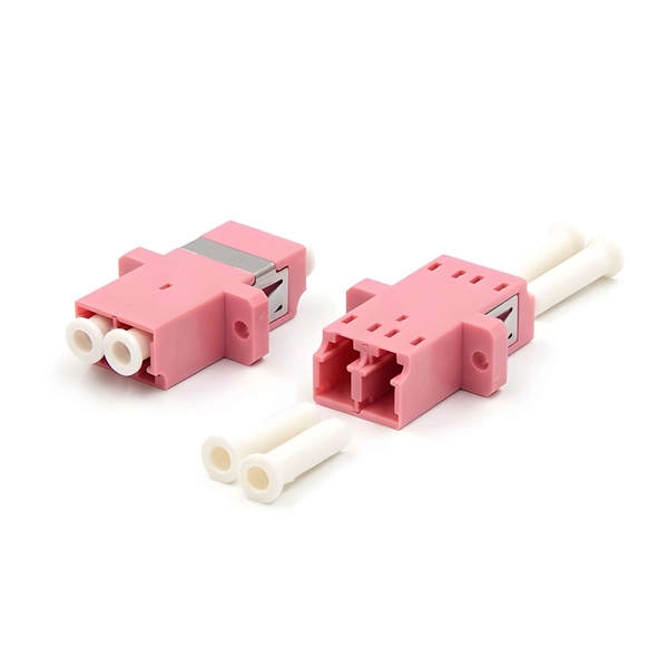
Common Fiber Optic Connector Model Designations
This guide explores the most common fiber connector types used in optical transceivers—LC, SC, FC, ST, and MPO/MTP—and highlights how LINK-PP integrates these connectors into its diverse range of optical transceiver products. Whether you're planning an FTTH deployment, upgrading a data center, or working in telecom infrastructure, this guide will help you make informed decisions. This article explores the wide range of fiber optic connector types, from legacy SC and ST to modern MPO/MTP and VSFF designs. Learn how each connector works, where it's used, and how to choose the right option for today's high-density, high-speed networks. Fiber optic connectors may look small. Fiber optic connectors are essential components in modern communications networks, enabling seamless data transmission over long distances with minimal losses. So, why are these connectors so.
[PDF Version]
-

The fiber optic cold connector broke inside
This guide provides a detailed roadmap for locating and fixing fiber optic cable breaks, covering detection techniques, repair methods, and best practices. The actual steps may vary depending on the cable and/or connectors. Any ideas about how to get someone to do a new connector for me? Initial google suggests I want a field termination rather than a splice. Any advice would be. Understanding the visual signs of fiber damage, knowing how to test them, and applying proper maintenance methods can dramatically reduce downtime and improve network reliability.