-
Color order of optical fibers and pigtails
This guide explains the latest EIA/TIA-598-D fiber color-coding standard used to identify fiber types, inner fiber sequences, and connector polish styles. With clear tables and updated details, it serves as a comprehensive reference for technicians handling modern fiber optic. Understanding fiber‑optic color codes is essential for any technician tasked with installing, maintaining, or troubleshooting modern fiber networks. In the photos above, on the left is a 1728 fiber cable with color coded buffer tubes, in the center are (from the top) singlemode zipcord cable used for patchcords with each fiber color coded, and on the right, a yellow. The color arrangement for optical fiber cables is standardized to ensure consistent identification of individual fibers during installation, splicing, and maintenance. Fiber optic cables are the arteries of modern communication—from data centers to factories, these slim strands of glass move terabits of information every second.
[PDF Version]
-
Can optical fibers be connected in series
It is worth noting while one optical core can connect to multiple terminal devices in a series. Consequently, long-distance transmission may not be feasible or experience significant signal. The number of optical cores in an optical fiber is the total number of equipment interfaces multiplied by 2, plus 10% to 20% of the spare quantity, and if the communication mode of the equipment has serial communication and equipment multiplexing, you can reduce the number of cores. Fusion Splicing: This method involves aligning the ends of the two fiber optic cables and then fusing them together using heat. This creates a permanent and low-loss connection. A verification email has been sent to {0}. Most systems operate by transmitting in one direction on one fiber and in the reverse direction on another fiber for full. An optical fiber connector is used to join optical fibers where a connect/disconnect capability is required.
[PDF Version]
-
Advantages and disadvantages of plastic optical fibers in sensors
Explore the benefits and drawbacks of Plastic Optical Fiber (POF), including cost, flexibility, attenuation, and temperature sensitivity. It's also known as “all plastic fiber. ” These fibers are typically manufactured using a simple liquid phase double crucible method. Using Polystyrene (PS) as the core. Optical fiber sensors have several advantageous features: they are compact, lightweight and enable the implementation of multiplexing schemes. Glass Optical Fibers: Made of high-purity silica glass with core diameters typically 10 to 100.
-
Are two single-mode optical fibers the same
Single fiber modules (BiDi) use one fiber for both transmitting and receiving data. They are easier to set up and give steady communication. Although they can do the same job in some instances, the different construction methods make each of them better suited to certain tasks and budgets. That makes picking between single mode and multimode fiber optic cables an. At their core, all optical fibers perform the same fundamental task – guiding light through a transparent medium with extremely low loss. Yet subtle differences in structure, materials, and modal behavior create distinct fiber types optimized for very different performance regimes. Understanding. In this in-depth single mode vs.
-
Temperature Measuring Optical Cable Fusion Splice Terminal
As heat sources in the fiber laser system, fusion points are among the most vulnerable parts in high power fiber lasers (HPFLs). A model is built to evaluate the heat induced by fusion splices quantitatively.
-

How to connect and splice optical cables in series
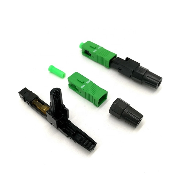
The simplest method: connect two cables pre-connectorized via a coupler (also called an adapter). The coupler aligns the two ferrules of the connectors using a zirconia sleeve. Before jumping into the physical steps, it's important to understand the two primary methods of fiber splicing: fusion splicing and. Fiber optic cable splicing involves joining two fiber optic cables together. Another method of connecting optical fibers is termination or connectorization, which consists of processing the end of a fiber optic bundle so that it can be connected to other fibers or devices through fiber optic. Connecting fiber optic cables requires precision and care due to the delicate nature of the fibers. At Turn-Key. Proper connection of fiber optic cables is essential to harness these benefits fully, as even minor errors can lead to significant performance issues like signal loss.
[PDF Version]
-
Number of cores in optical cables and optical fibers
Generally speaking, the number of optical cores in an optical fiber is the total number of equipment interfaces multiplied by 2, plus 10% to 20% of the spare quantity. The number of. This article will walk you through the basics of fiber optic cores and provide practical guidance for selecting the suitable fiber optic cable to meet your networking needs. The core is surrounded by a medium with a lower index of refraction, typically a cladding of a different glass, or plastic. Light. Unlike copper wires, which are limited by lower data transmission speeds, shorter transmission distances, and higher susceptibility to electromagnetic interference, fiber optic cables offer unparalleled performance and can cover much greater distances without bumping up against signal degradation. However, if there were no cores, fiber optic cables would be useless.
[PDF Version]
-
10 Gigabit Ethernet card optical module not connected to fiber optic cable
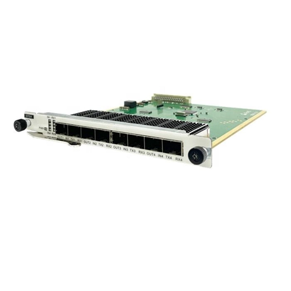
Troubleshooting SFP+ link issues in 10 GbE networks requires attention to module type, match of speed and wavelength, clean fiber connections, correct configuration, thermal management, and equipment compatibility. You can quickly resolve SFP+ Module connectivity issues by following a systematic optical transceivers troubleshooting process. Check for common connection problems, such as link failures or modules not recognized. Check compatibility between the optical module and switch Most switch brands have specific compatibility requirements. During network upgrades, many enterprise users encounter a common issue: after replacing 10G broadband lines or inserting 10G SFP+ optical modules, the switch still fails to operate at full 10G bandwidth or even fails to recognize the modules. We've listed the five most common ones. First of all, let's briefly recap what SFP and SFP+ stand for. SFPs – short for 'small form-factor pluggable' – are compact, hot-pluggable devices.
[PDF Version]
-
Optical communication products specifically refer to
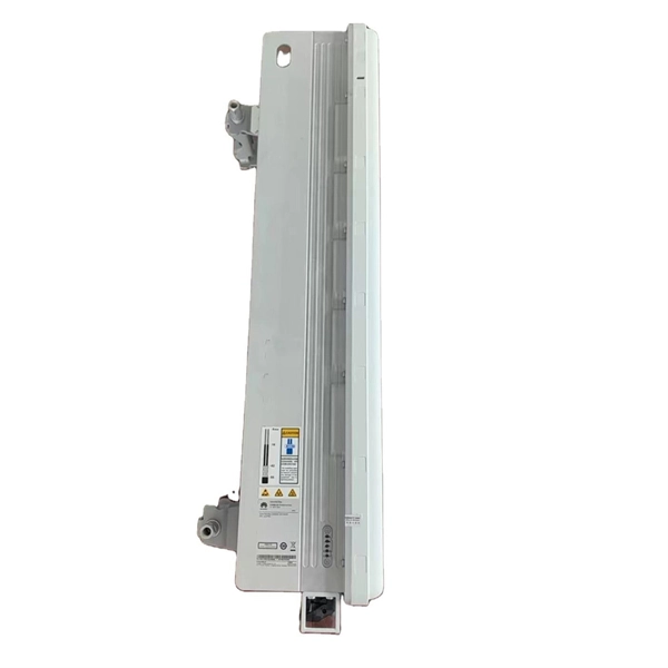
Modern communication relies on optical networking systems using optical fiber, optical amplifiers, lasers, switches, routers, and other related technologies. Optical communication, also known as optical telecommunication, is communication at a distance using light to carry information. It can be performed visually or by using electronic devices. The earliest basic forms of optical communication date back several millennia, while the earliest electrical. Therefore, NASA is developing optical communications to address limitations of radio frequency (RF) communications, including: bandwidth, spectrum and overall size of frequency packages and power used.
-
Direct Sales of Gigabit Optical Modules from Manufacturers in Mali
U.S. exporters should identify a local agent or distributor to assist in bringing goods to market in Mali. Businesses should be aware, however, that entering a successful partnership or representational relatio.
-
Does the FC interface transmit optical or electrical signals
The FC-0 specification includes cables, connectors, and optical and electrical parameters for a variety of data rates. This connector landscape reflects how modern SFP deployments prioritize port density and. Physical Fibre Channel (FC) is a high-speed data transfer protocol providing in-order, lossless delivery of raw block data. Fibre Channel is primarily used to connect computer data storage to servers in storage area networks (SAN) in commercial data centers. Host Bus Adapter (HBA) An HBA is a dedicated hardware component that connects a server to a Fibre Channel storage. Traditionally, compute operating systems have communicated with peripheral devices over channel connections, such as Enterprise Systems Connection (ESCON) and SCSI. Channel technologies provide high levels of performance with low protocol overheads. The connector mechanically orients the fiber cores, allowing light to pass and travel through.
[PDF Version]
-
How to convert an electrical port to an optical port on a switch
A switch SFP port converts electrical signals into optical signals via SFP transceivers, or maintains them electrically for copper connections. By using an SFP to RJ45 adapter (e. 5G SFP), you can seamlessly connect legacy Ethernet devices to modern fiber-optic. The RJ45 port is a built-in electrical port of a Gigabit Ethernet switch, and it is mainly connected by Category 5, Category 5e, Category 6, and Category 6e twisted-pair cables. However, modern networks often combine both technologies. The good news: you can bridge them easily using the right hardware, such as media. An SFP port on a switch or router SFP port enables network engineers to connect multiple media types, from fiber optic links to copper Ethernet. An SFP transceiver acts as a compact, hot-swappable optical transceiver that.