-
Method for bundling optical cables
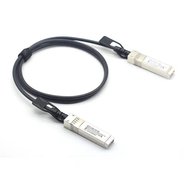
Fiber optic splicing is often the preferred way to connect two fiber optic cables because it has lower light loss (attenuation) and back reflection than connectorization. Fusion splicing and mechanical splicing are the two most common methods of fiber optic splicing. AOCsarrive. This document describes the specifications for preparing, routing, and bundling cables and attaching labels to these cables. Another method of connecting optical fibers is termination or connectorization, which consists of processing the end of a fiber optic bundle so that it can be connected to other fibers or devices through fiber optic. In the rapidly evolving fields of telecommunications, medical imaging, and industrial sensing, fiber optic bundles serve as the cornerstone for efficient and reliable data transmission.
-
How to calculate the number of fiber optic cables for users
The number of fiber strands is determined by the installation requirements, such as the number of switches or devices being connected and the type of application. This guide walks you through the simple decision steps engineers use, the common strand counts on the market, and clear rules-of-thumb for different project. This calculator keeps service strands, growth reserve, and spare capacity separate so the final cable count is easy to audit. Where is the cable going? Indoors or outdoors? Do you need singlemode or multimode fiber? How many fibers do you need in your cable? What length does the cable need to be? What connectors do you. A tool that computes how many fibers fit in a circular bundle and splits them into user-defined segments for cable-assembly planning. Key Parameters: • Center Diameter, Fiber Diameter, Packing Efficiency, Section Count Calculation: Visualization: • Color-coded radial diagram with per-section. Fiber optic network design refers to the specialized processes leading to a successful installation and operation of a fiber optic network. This helps reduce waste, manage costs, and achieve a clean, efficient installation.
[PDF Version]
-
Number of cores in optical cables and optical fibers
Generally speaking, the number of optical cores in an optical fiber is the total number of equipment interfaces multiplied by 2, plus 10% to 20% of the spare quantity. The number of. This article will walk you through the basics of fiber optic cores and provide practical guidance for selecting the suitable fiber optic cable to meet your networking needs. The core is surrounded by a medium with a lower index of refraction, typically a cladding of a different glass, or plastic. Light. Unlike copper wires, which are limited by lower data transmission speeds, shorter transmission distances, and higher susceptibility to electromagnetic interference, fiber optic cables offer unparalleled performance and can cover much greater distances without bumping up against signal degradation. However, if there were no cores, fiber optic cables would be useless.
[PDF Version]
-
Cost of laying optical cables using the airflow method
Prices vary based on the length of cable needed, installation method (aerial or underground), and labor rates in your area. Expect to pay $1 to $12 per linear foot, depending on project complexity and materials. By decoupling the empty microduct installation from the fiber blowing process, network operators can achieve up to 70% reduction in initial capital expenditure. Buying fiber optic installation services involves several cost components, with total price influenced by length, location, and access. Mainly manual. A fiber optic cable is made up of ultra-thin strands, each capable of carrying huge amounts of data at the speed of light. These strands are as fine as a human hair and are engineered for high-performance data transmission.
-

How to calculate the number of cables a cable tray can hold
The formula used to calculate cable tray capacity is: Cable Tray Capacity = (Tray Width × Tray Depth × Fill Ratio) / Cable Cross-sectional Area Where: Tray Width is the internal width of the cable tray in meters (or millimeters). A Cable Tray Capacity Calculator is an essential tool for electrical engineers, contractors, and project managers involved in the installation and management of electrical cables. For mixed cables, sum the areas of all individual cables. Enter the dimensions of the cable tray, the desired fill ratio, and the diameter of the cables to calculate the cable tray capacity.
-
Calculation of the number of network patch panels
As a rough guideline, most organizations install between 24 and 48 ports per patch panel and use a maximum of four to six patch panels per rack. Basic Concepts and Classification of Fiber Optic Patch Cords Fiber optic patch cords are fiber cables terminated with. Some of the key considerations include: Number of ports: Choose a patch panel with the right number of ports to accommodate your network devices. Mounting options: Consider the mounting options for the. A patch panel is a hardware device that connects multiple network circuits in a central location, which acts as a hub for all network connectivity. When it comes to patch panels per rack, there is no hard and fast rule. It all depends on the requirements of the organization or the enterprise. For example, for structured cabling that might "want" wall-mount patch panels on either end of pieces of conduit, combined with in-rack patch panels. A bulk (multi-strand) fiber cable enters the patch panel and then each fiber strand is separated into individual strands or pairs of strands.
[PDF Version]
-
Minimize the number of joints in optical fiber communication cables
When configuring the disk, try to make the entire disk configuration (single plate ≥ 500 meters) to minimize the number of joints. Optical fibers can be joined together, such that light is efficiently transferred from one fiber to another. That is usually done for permanent connections, but it. Fiber optic joints or terminations are made two ways: 1) splices which create a permanent joint between the two fibers or 2) connectors that mate two fibers to create a temporary joint and/or connect the fiber to a piece of network gear. Mechanical splicing involves physically. The handbook provides guidelines for the jointing of optical fiber cables, emphasizing the importance of effective jointing techniques to minimize signal loss.
-

Calculation method for beam splitter
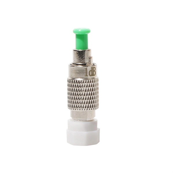
A beam splitter divides incident light into reflected and transmitted beams at a specified R/T ratio. For a lossless beam splitter, R + T = 1. One of the biggest challenges for modeling such a system is that multiple ray paths cannot be simultaneously traced in Sequential Mode. Thus, multiple configurations are needed to trace rays along both the transmitted and. Three techniques to model diffractive beam splitters – two in Sequential and one in Non-Sequential modes: 2. Method A: Diffraction Grating surface and multi-configuration 2. Development steps Inserting general parameters for simulation (wavelength, aperture,. Field 1 evolves as E1 ! T E3 + RE4, where T; R are the transmission and re ection coe cients for the beam splitter. The transformation matrix is then given by. Separate (focused) beams or light points are of interest for a wide range of applications, whether for manufacturing processes, for special fiber coupling, for face recognition systems or light marker generation.
[PDF Version]
-

Laying optical cables in the trough
A practical, engineering-focused guide to planning and installing underground fiber optic cables with the right cable structure, trench design and protection level for long-life, low-risk networks. They're ideal for harsh environments due to their chemical and UV resistance, and they're also fire and non-conductive for safety. With low maintenance needs, a long lifespan and recyclability, GRP. From bustling industrial complexes and hyperscale data centres to cross-country rail systems, the ever-so-dependable cable trough plays a crucial role in contemporary cable route management. The Fiber Optic Association, Inc. The charter of the FOA was to promote professionalism in fiber optics through education, certification, and. Below is given the fiber optic cable installation method statement for performing the installation of optical fiber cabling system for any kind and size of project.
[PDF Version]
-
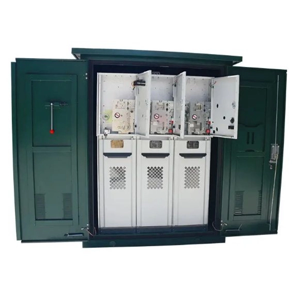
Are cables pre-installed in the distribution box
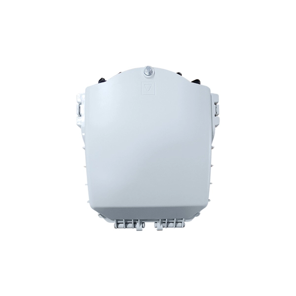
Each unit will have its own coaxial cable drop from the nearest intermediate/main distribution frame terminal/cabinet to the unit with no additional splices/splitters between the unit and the intermediate/main distribution frame coaxial terminal/cabinet. Choose the right box based on environment (indoor/outdoor), load capacity, and durability. Check for proper IP/NEMA ratings and material quality. Ensure safe placement: install in dry, accessible areas with good ventilation and at appropriate height (typically ~1. Practice good wiring: secure. The Fiber Optic Distribution Box is a multifunctional termination point to connect feeder cables with drop cables in FTTX communication network systems.
-
How to splice outdoor optical cables
Learn how to splice fiber optic cable using fusion splicing with this complete step-by-step guide. Includes tools, best practices, loss standards (ITU-T G. 652), cost analysis, and FAQs for network engineers and installers. Ensure Your Splicing Tools are Clean – #2. Regardless of the type of fiber network you're deploying, be it for telecom, enterprise data centers, or smart city infrastructure, fusion splicing provides the benefits of. Fusion splicing is a precise and permanent method for joining two fiber optic strands, ensuring the integrity and performance of the optical network. The guide explains that determining if the cable is direct bury rated or if it. Fiber optic joints or terminations are made two ways: 1) splices which create a permanent joint between the two fibers or 2) connectors that mate two fibers to create a temporary joint and/or connect the fiber to a piece of network gear.
[PDF Version]
-
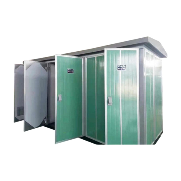
How many meters should the cables be spaced in the distribution box
At the highest end, voltages above 75kV require at least 4 meters of space on all sides. The last rule has to do with general fire danger. Calculate and select the right number and spacing of cables for junction boxes using NEC guidelines to ensure safe, code-compliant electrical installations. The previous code language could technically allow an unlimited length of coiled up NM cable inside the wall as long as it was secured within 12 inches of the box. In the 2020 NEC ®, no. Choose the right box based on environment (indoor/outdoor), load capacity, and durability. Check for proper IP/NEMA ratings and material quality. NEC Article 408 covers switchboards, switchgear, and Panelboards installation and applications. 1) For NM cable, specifically 300. If these requirements cannot be met then a steel plate commonly referred to as a nail plate can be used to secure the wire.
[PDF Version]