-
Installation method of cable tray in distribution box
Spring knot is used to connect cable tray or trunking to channel. Approved and correct fittings are used. Installed containments are free of damages. Whether you're building a commercial setup or upgrading an industrial plant, proper cable tray installation ensures neat wiring, safe access, and easy maintenance. But before you lay the first tray or clamp down a single cable, you need a solid plan. This guide breaks down the process step by step. This guide covers the critical steps, from selecting the right electrical cable tray and performing accurate cable fill. maintain spacing or to keep cables in place when the tray is ect the minimum bend ra-dius for cables as they exit the bottom of the cable tray. A rung spacing of 6 to 9 inches (150 to 230 mm) is preferable when the cable tray cont d for instrumentation and control applications that require. Below is the detailed cable tray installation method statement not only for cable tray but also applicable for GI ladder and trunking for indoor and outdoor applications and in service rooms like pump rooms, electrical rooms and plant rooms etc.
[PDF Version]
-
Cable tray internal wiring installation
Proper planning for installing cable tray includes calculations based on loading, support systems, cable/wire fill and spacing, conductor types, securing of the cables and wire, and proper grounding and bonding are all important aspects of cable tray installation. NEMA VE2 addresses cable tray installation and provides information on maintenance and system modification. The following pages address the 2014 National Electrical Code® requirements for cable tray systems as well as design solutions from practical experience. headquartered manufacturer with over 130 years of supplying solutions for the electrical and data markets. Hubbell's strength is demonstrated by a long-standing reputation for supplying reliable. en completely installed, without damage either to conductors or structural system use maintain spacing or to keep cables in place when the tray is ect the minimum bend ra-dius for cables as they exit the bottom of the cable tray. A rung spacing of 6 to 9 inches (150 to 230 mm) is preferable when. How about organizing your wiring with a cable tray system? Smart move.
[PDF Version]
-
Requirements for Cable Trench and Cable Tray Installation
This article provides a comprehensive framework that governs various aspects of cable tray installations, including the types of cables that are deemed acceptable for use, requirements for grounding and bonding, and stipulations regarding tray fill capacity. Additionally, it addresses critical. NEC Article 392 outlines the key rules for installing and maintaining industrial cable tray systems. These systems, made from metal or plastic, are open structures designed to support electrical conductors, ensuring proper organization and safety. This installation is for underground services from 2001 amps to 4000 amps. The following pages address the 2014 National Electrical Code® requirements for cable tray systems as well as design. Cable tray systems provide a safe, organized, and flexible method for supporting insulated conductors and cables in commercial and industrial electrical installations.
[PDF Version]
-
Cable Tray Internal Wiring Method
NEC Article 392 explains cable trays, their components, appropriate wiring methods for cable trays, and instances where they are and are not permitted for use. It also focuses on construction and installation practices for cable trays. Here is the summary of the main points found. Hubbell Wiring Device-Kellems and Hubbell Premise Wiring are divisions of Hubbell Incorporated, a U. headquartered manufacturer with over 130 years of supplying solutions for the electrical and data markets. The Cable Tray ng standards, performance standards, test standards and application in this document have been tested extens ompetent professional en completely installed, without damage either to conductors or. The B-Line series Cable Tray Manual was produced by our technical staff. Cable trays give cables a clear path.
-

Cable tray installation platform price
Compare cable tray costs by type, material, and installation. Find the most cost-effective option for your project in this detailed buyer's guide. Cable tray installation cost per meter varies by specifications; GangLong Fiberglass offers kits for raised floor system and facility needs. Over the past 55+ years, MP Husky US Cable Tray has engineered and manufactured the most reliable, highest quality, cost effective and innovative cable trays systems. Cable tray pricing depends on materials, coatings, size, supplier margins, and order quantity —plus hidden costs like shipping and installation. This guide breaks down everything buyers need to know, from price trends to cost-saving tips. The price is based on standard length of the cable tray which is 2.
-
Cable tray installation includes fireproofing and sealing
Cable trays and busways at floor level or at slab penetrations shall have a waterstop no less than 50 mm in height. At slab penetrations, provide 20–30 mm of firestopping and install a fire-support plate at the top. Sealing shall be tight and reliable, without visible. FireResistant Solutions provides cable tray covering and fire-protection systems designed to safeguard electrical and data infrastructure in commercial and multifamily buildings. Route. Where cables pass through shafts, walls, slabs, or enter electrical panels or cabinets, openings shall be tightly sealed with firestopping materials in accordance with design requirements. This organic/inorganic elastomeric sheet is. SpecSeal Quick Clip Insulation Hangers are designed to accelerate the installation of curtain wall insulation for perimeter fire barrier systems. They provide robust support for cables while ensuring fire safety in extreme conditions.
[PDF Version]
-
No supports are allowed at the cable tray connection points
Support spacing for cable trays must align with the manufacturer's instructions, as outlined in NEC 392. Generally, standard trays require supports every 6 to 10 feet, while heavy-duty, long-span trays can handle distances of up to 20 feet between supports. This is a description of how to select, install, and support these metal or plastic frames, on which electrical wires are installed. Here's what you need to know: Cable Types: Only use. Cable trays can be part of a planned cable management system to support, route, protect, and provide a pathway for cable systems. Power, low voltage control, data, or telecommunications wiring distribution systems can be used with cable trays. Cable trays can provide a safe component of a power, low voltage.
-

How much distance should there be between the cable tray and the side support
For horizontal sections where cable trays are laid out in a straight line, the typical support span (distance between supports) should range from 1. This range allows for easy access and efficient maintenance. The NEC requires that cable trays must be supported by members at an interval specified by the cable tray manufacturer, but not more than 5 feet for horizontal runs to support the weight of the cables and other loads. According to the regulations under NEC 392. 10 (B) (1), the smallest size single conductor allowed to be installed in a cable tray is 1/0 AWG. For the installation of single conductor cables sized 1/0 AWG to 4/0 AWG in industrial establishments, the NEC specifies the maximum allowable rung spacing for the cable. Unlike a simple wire trough, which is typically a covered channel for shorter runs, cable trays provide a comprehensive support system for complex wiring paths over long distances. A well-planned cable tray installation not only organizes conductors but also provides protection and makes future.
[PDF Version]
-
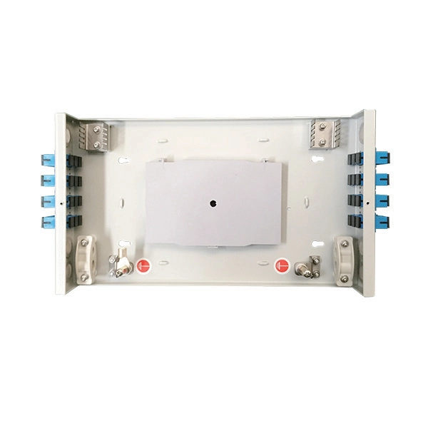
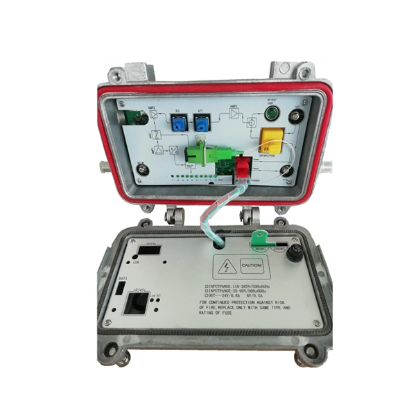
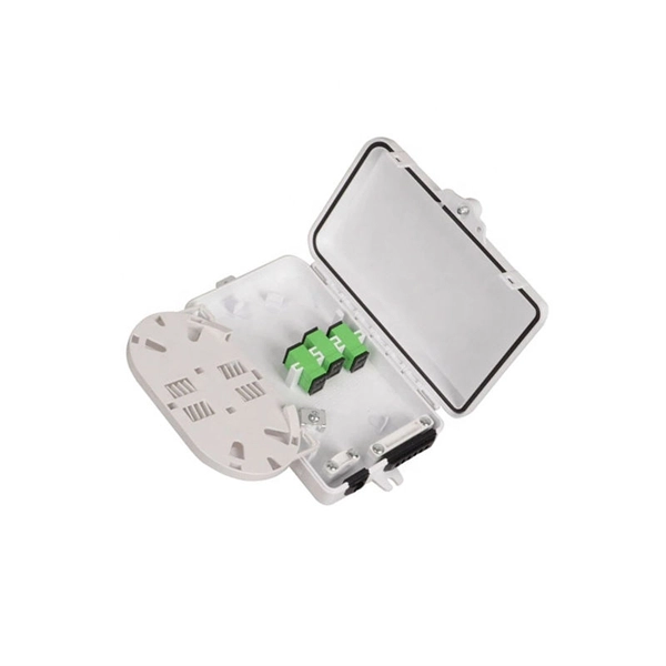
Correct wiring method for jumpers fiber optic cable
Three Polarity Connections Different polarity methods use different kinds of MPO trunk cables. However, all methods utilize duplex patch cords to form fiber optic links. The TIA standard also defines two different types of LC or SC duplex fiber optic patch cords to complete. optic cable is sensitive to excessive pulling, bending, and crushing f rces. Consult the cable specification sheet for the cable you are installing Do not bend the cable more sharply than the minimum recomme ded bend radius. Patch cords are more prone to damage than fiber optic cables, especially. Good management of fiber jumper can not only reduce the operating cost of the entire fiber optic network, make it beautiful and convenient, but also increase the reliability and flexibility of network operation and maintenance. Fiber Cabling and Management In the process of installing and arranging. The Fiber Optic Association, Inc. There are various kinds of fiber jumper cables, including single mode and. How to connect the fiber optic jumper?Optical fiber jumper is a connection line used to connect optical fiber equipment,which plays a vital role in optical fiber communication.
[PDF Version]