-
What thickness of cable tray trough meets national standards
Another advantage of this method is coating thickness. 50 ounces per square foot on each side, or a total 3. All rights, including translation into other languages, reserved under the Universal Copyright Convention, the Berne Convention for the Protection of Literary and Artistic Works, and the International and Pan American copyright conventions. The information in this publication was considered. The national standard for cable tray thickness specifies the minimum allowable plate thickness for different The national standard for cable tray thickness specifies the minimum allowable plate thickness for different specifications of steel bridge, FRP bridge and aluminum alloy bridge. A rung spacing of 6 to 9 inches (150 to 230 mm) is preferable when the cable tray cont d for instrumentation and control applications that require. C C ble Trough e Height T e Height T h Heig e # Si 5 – 2. Level of Harmonization This standard uses an IEC format, but is not based on, nor is it to be considered equivalent to, an IEC standard.
[PDF Version]
-
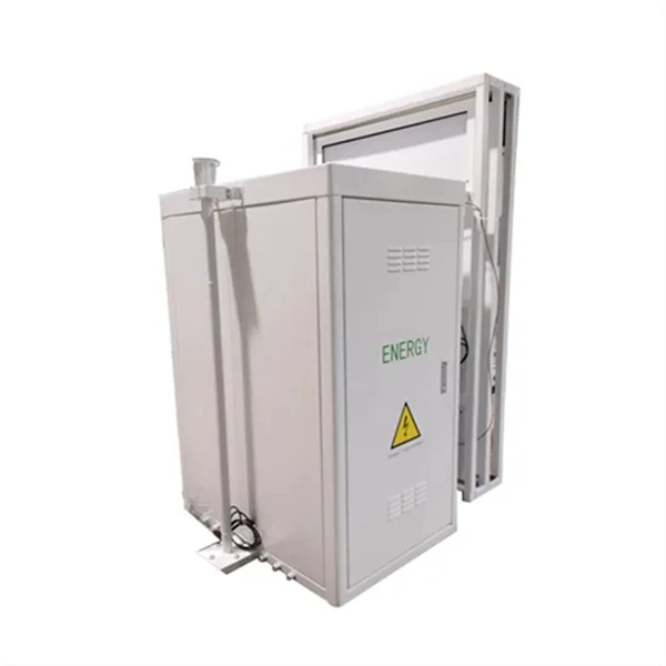
Cable Wiring Standards for Integrated Cabinets in Different Areas
This pocket guide provides an overview of the requirements for the installation of cables concealed in structures in accordance with regulation group 522. 6 of BS 7671:2018+A2:2022 (IET Wiring Regulations 18th Edition). In the industrial sector, electrical cabinets play a crucial role in distributing, protecting, and controlling electrical power. The NFC 15-100 standard is the primary benchmark. Running electrical wiring inside kitchen cabinets requires balancing aesthetic goals with strict safety and electrical code requirements. Cabinets are often the only way to route power to modern conveniences without opening walls, making this a common necessity in remodeling and new construction. Jump directly to This guide is intended to assist code authorities, installers and contractors in determining the suitability of UL Certified, Listed. This handbook is provided for the use of all Departments of the ITER Organization and is addressed primarily to system specifiers, designers and users of electrical components in otherwise non-electrical plant systems, rather than to designers of the power supply systems.
[PDF Version]
-
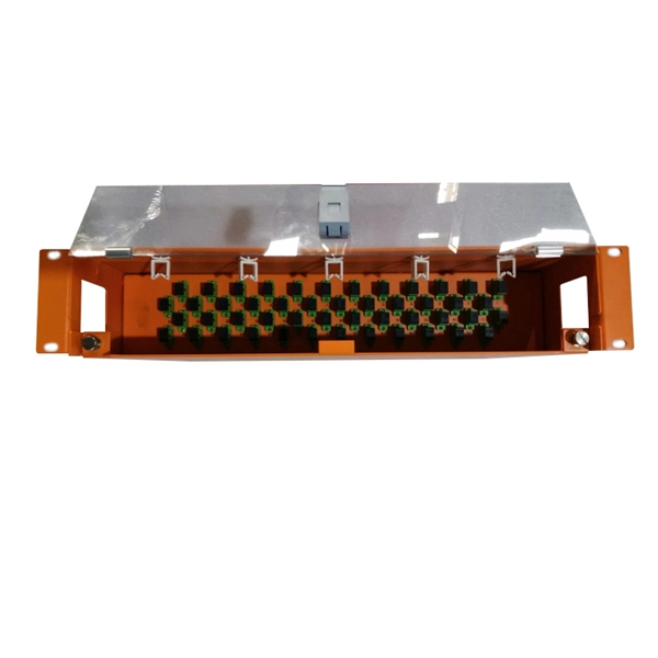
Latest Standards for Fiber Optic Cable Layer Classification
3‑E “Optical Fiber Cabling and Components Standard” was developed by the TIA TR‑42. Scope: This Standard specifies performance, transmission, and test and measurement requirements for premises optical fiber cable. The Fiber Optic Association, Inc. (FOA) was founded in 1995 to help develop the workforce to build the fiber optic networks to support a rapid expansion in communications and the Internet. The charter of the FOA was to promote professionalism in fiber optics through education, certification, and. The International Electrotechnical Commission (IEC) and the Telecommunications Industry Association (TIA) create detailed rules for fiber optic components, manufacturing, and testing. These standards focus on things like connector geometry, ferrule cleaning, and insertion loss testing. It covers the environmental and length-related.
-
Inspection Standards for Cable Tray Bridging
Why It Matters: Separation violations are among the most common inspection failures, often delaying turnover or requiring costly rework. 136, and 805 routing rules consistently in risers, plenums, and shared pathways. In addition, this document contains several references to provisions of the National Electric Code (NEC), which is published by the National Fire Protection Association (NFPA). Mandatory inspection items (directly rework if unqualified) The metal bridge must be provided with protective grounding (PE) All galvanized, steel, and aluminum alloy trays must be grounded, except for non-metallic trays. Best Practice: Maintain TIA‑569‑E spacing between power and LE circuits. Why Are Cable Tray Inspections Important? Cable trays serve as the backbone of electrical systems, ensuring. These systems provide an efficient and adaptable solution for managing a wide range of cables, including power cables, control cables, Ethernet, and fiber optic lines. The process described here takes a systematic approach to ensuring that cable tray installations meet safety, reliability, and project-specific needs while following to.
[PDF Version]
-
National Standards for Cable Trays and Ladders
The National Electrical Manufacturers Association (NEMA) VE 1 standard is the primary guideline for specifying cable tray systems, particularly defining load capacity and span capabilities. This standard specifies the requirements for nonmetallic cable trays and associated fittings designed for use in accordance with the rules of the Canadian Electrical Code (CEC) Part 1, and the National Electrical Code® (NEC). The Bulletin is advisory in nature, informational in content, and is intended to assist employers in providing a safe and healthful workplace. These systems provide an efficient and adaptable solution for managing a wide range of cables, including power cables, control. In this installment of our Code Corner series, Ryan Mayfield focuses on the 2023 National Electrical Code (NEC) changes concerning cable trays, particularly section 690.
[PDF Version]
-
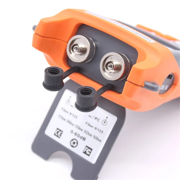
Testing Standards for Power Fiber Optic Cable Trunk Lines
FOA procedures, such as OFSTP-7 (single-mode) and OFSTP-14 (multimode), align with TIA and IEC standards. FOA standards help you with installation, testing, and troubleshooting in real-world conditions. These parameters ensure your network meets performance and compliance requirements. You need to measure how much signal is. d suppliers of electrical construction services. Existence. ANSI/TIA‑568. 3‑E “Optical Fiber Cabling and Components Standard” was developed by the TIA TR‑42. Scope: This Standard specifies performance, transmission, and test and measurement requirements for premises optical fiber cable. A practitioner-level walkthrough of the IEC 60794 framework: standard structure, mechanical and environmental test methods, type vs routine testing, common failure modes, and procurement specification guidance. Fiber optic testing of a newly installed system not only verifies that the system meets its design requirements, but also creates a performance baseline for all future testing and troubleshooting of t at system. The Contractor must utilize the correct equipment and testing techniques to gain acceptance, or the work cannot be approved.
[PDF Version]
-
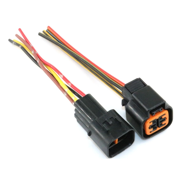
What is a fiber optic cable with a connector called
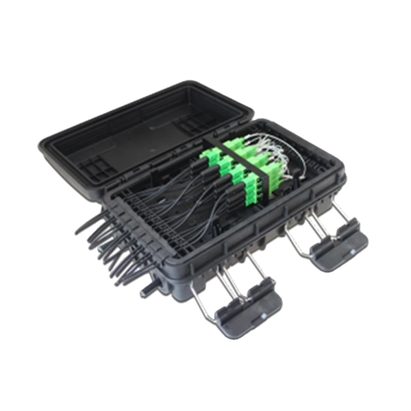
The fiber connector types, sometimes referred to as terminations, link fiber optic cables together through terminals, switches, adapters, and patch panels, by bridging the gap between their internal glass fibers that transmit the data down the length of the cable. An optical fiber connector is used to join optical fibers where a connect/disconnect capability is required. They come in various types like SC, LC, ST, and MTP, each designed for specific. The fiber connector is called a fiber optic or optical fiber connector.
-
How to pull up a power fiber optic cable
Fiber optic cables should always be pulled by the strengthened yarn fibers inside the outer jacket. This article explores recommendations for pulling and installing fiber optic cable. Most fiber optic cables boast a pull strength of 100 – 200. Fiber optic cable is surprisingly strong, durable and pliable; however, several best practices should be followed to ensure a successful cable installation. Most fiber damage does not come from normal operation after the system is live. More than half of cable problems happen because of wrong pulling. In 2025, new tools like hydraulic blowers, smart monitors, and better grips help you lower risks, save money, and keep the. A duct is available from point A to point B, a pull tape is blown in, a fiber optic cable is attached to it and the cable is pulled through the duct.