-
How to pull up a power fiber optic cable
Fiber optic cables should always be pulled by the strengthened yarn fibers inside the outer jacket. This article explores recommendations for pulling and installing fiber optic cable. Most fiber optic cables boast a pull strength of 100 – 200. Fiber optic cable is surprisingly strong, durable and pliable; however, several best practices should be followed to ensure a successful cable installation. Most fiber damage does not come from normal operation after the system is live. More than half of cable problems happen because of wrong pulling. In 2025, new tools like hydraulic blowers, smart monitors, and better grips help you lower risks, save money, and keep the. A duct is available from point A to point B, a pull tape is blown in, a fiber optic cable is attached to it and the cable is pulled through the duct.
-
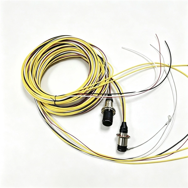
What is a fiber optic cable with a connector called
The fiber connector types, sometimes referred to as terminations, link fiber optic cables together through terminals, switches, adapters, and patch panels, by bridging the gap between their internal glass fibers that transmit the data down the length of the cable. An optical fiber connector is used to join optical fibers where a connect/disconnect capability is required. They come in various types like SC, LC, ST, and MTP, each designed for specific. The fiber connector is called a fiber optic or optical fiber connector.
-
Cable tray dip coating process
Steel trays get dipped in very hot molten zinc (around 450°C). The zinc bonds tightly to the steel, creating a thick, tough layer. Process: Degreasing → Pickling → Rinsing → Fluxing → Drying → Hot-dip galvanizing → Cooling → Passivation (optional) → Inspection. Hot-dip galvanizing is a process that enhances the durability of cable trays by creating a protective zinc coating, safeguarding them from corrosion. It is cost-effective, protects against a wide variety of environmental chemicals, and is self-healing if an area becomes unprotected through cuts or scratches. Steel is coated with zinc through electrolysis by dipping steel into a bath of. Legrand's offer of global solutions for wiremesh cable trays (and accessories) is one of the most complete on the market. It offers true freedom by allowing multiple configurations in a wide choice of finishes for optimal integration into any environment.
[PDF Version]
-
What are the requirements for cable tray installation in factory buildings
Only approved tray-rated cables should be installed. Grounding and bonding are mandatory for metallic trays. Tray fill limits must be calculated properly. Mesh trays reduce installation time while. Cable tray systems provide a safe, organized, and flexible method for supporting insulated conductors and cables in commercial and industrial electrical installations. When properly selected and installed, cable trays simplify routing, improve accessibility, and support future expansion while. NEC Article 392 outlines the key rules for installing and maintaining industrial cable tray systems. These systems, made from metal or plastic, are open structures designed to support electrical conductors, ensuring proper organization and safety. 305(a)(3), or comparable standards promulgated by States operating OSHA-approved State plans. In addition, this document contains several references to provisions of the National Electric Code. The primary rulebook used in the safe use of cable trays is NEC Article 392.
[PDF Version]
-
Translate the cable tray by 45 degrees
To create a 45-degree bend, cut the side rails to remove a segment calculated by the formula (Tan (22. Google's service, offered free of charge, instantly translates words, phrases, and web pages between English and over 100 other languages. So basically from my middle line what size to mark either side to cut my lip away to create different angles. Calculate horizontal, vertical, or compound cable tray offsets based on bend angle, offset distance, and available installation space. Measure this distance along the straight tray. ADVANCED S PRODUCTS I ASP 45° inuous system as well as stand-alone elements. 5∘ cuts on two separate pieces of cable tray. The second piece's cut must be in the opposite direction. Easy step to make 45 degree offset cable tray/Pipe and Air duct Cable tray 90 Degree Bend ! Cable tray ( Hindi) Cable tray 22. Distance of 145 mm ×.
[PDF Version]
-
Metrology Standards for Cable Tray Supports
The International Electrotechnical Commission (IEC) provides detailed guidelines for cable tray systems under IEC 61537. This standard outlines the construction requirements, testing methods, and performance parameters for cable trays and related support systems. Covers construction and test requirements for. Cable tray systems provide a safe, organized, and flexible method for supporting insulated conductors and cables in commercial and industrial electrical installations. When properly selected and installed, cable trays simplify routing, improve accessibility, and support future expansion while. us-trations without notice.