-
The Role and Importance of Communication Power Systems
Power system communication networks play a critical role in the operation and management of modern electricity grids. These networks serve as the backbone for the seamless exchange of data between various components of power systems, including generation plants, substations, and. There are a several types of communication media such as micro wave, radio system, fiber optic, etc. Power system management functions are primarily divided into three interrelated areas: There are 3 distinct types of telecommunication networks. 2) Various communication schemes used including power line carrier communication, fiber optic communication, satellite communication and. The large-scale integration of converter-interfaced resources leads to the power grid transfor-mation from voltage-source-dominated to voltage-current-source-composite, which also raises new challenges to model and analyze the system synchronization.
[PDF Version]
-
Anti-residual power systems for wind power generation
A hybrid wind-solar energy system consists of the following components: 1. Solar panels 2. Wind turbine – see our guide to the best wind turbines 3. Charge controller 4. Battery bank 5. Inverter 6. Power dis.
-
DC busbar power failure
If the busbar protection fails to trip when an external fault occurs or if it falsely trips while in use, the power system could become unstable. A total power outage will result from this. Regular dielectric testing is crucial to verify the quality of insulation and ensure that busbars can perform reliably under both normal. Busbar insulators are the backbone of electrical systems, ensuring safe power distribution by isolating conductors and preventing faults. However, harsh operating conditions, material degradation, and improper maintenance can lead to insulator failures—jeopardizing safety and system reliability. The DC-link capacitor selection is one of the first and most important steps. Consequently, power busing design needs critical consideration in terms of performance under converter operation, asymmetric loading, short-circuits, thermal and insulation breakdown.
[PDF Version]
-
Why should the power supply to the small busbar be disconnected
To protect the bus from faults, it is mandatory to disconnect it from all the power sources as soon as possible. This means that, breaker CB-1, 2, 3 & 4 must open during actuation of busbar protection. You might think that only CB-1 should open. Busbar protection is a protection scheme meant to protect the busbar from electrical fault. Double Busbar arrangement or one and half breaker scheme. With increasing short-circuit power in the network. Disadvantages: Single bus-bar system has the following three principal disadvantages:- The bus-bar cannot be cleaned, repaired or tested without de-energizing the whole system. Thus, it is an electrical junction where all incoming and outgoing currents connect. Always use appropriate personal protective equipment, such as safety glasses and insulated gloves, and verify circuits are dead using a multimeter.
[PDF Version]
-
Function of the small busbar in the central power switch
The bus bar is a metal strip that distributes electrical current to the individual circuit breakers. In most assemblies you will find horizontal main bars, vertical risers, neutral and equipment-ground buses, and purpose-designed. What are Busbars, Bus Stabs, Circuit Spaces, Breaker Slots, Neutral Terminals, and Ground Terminals in an Electrical Panel or Load Center? Electric panels and load centers in residential and commercial applications have some different setting for breaker installation ad load circuit distribution. They connect directly to the main power source and are designed to handle high current loads safely. Circuit Breakers act as protective devices within the panel.
-

How to route fiber optic cables for high-voltage power lines
This technique takes a small, lightweight fiber optic cable and wraps it around or lashes it to the power line. The cable is called optical power attached cable (OPAC), and it is lashed to the power cable with a specialized tool that is pulled from the ground, such as a. Installing ADSS (All-Dielectric Self-Supporting) cables near live power lines demands precision, compliance with safety standards, and an understanding of high-voltage risks. This guide from GL FIBER breaks down the process into actionable steps, aligned with IEEE 524 and IEC 61935-1 protocols, to. Most aerial fiber optic cables are installed by lashing to a steel messenger wire strung between poles, but there is a category of cables with special high-strength jacket designs called all-dielectric self-supporting (ADSS) cables. ADSS cables are designed to withstand very high-tension loads. bles in a high voltage environment, with typical line voltages of 115 kV or more, requires the evaluation of certain critical parameters. Curr ntly, there are a limited number of industry documents that address the requirements for optical fiber cables near high voltage circuits.
[PDF Version]
-
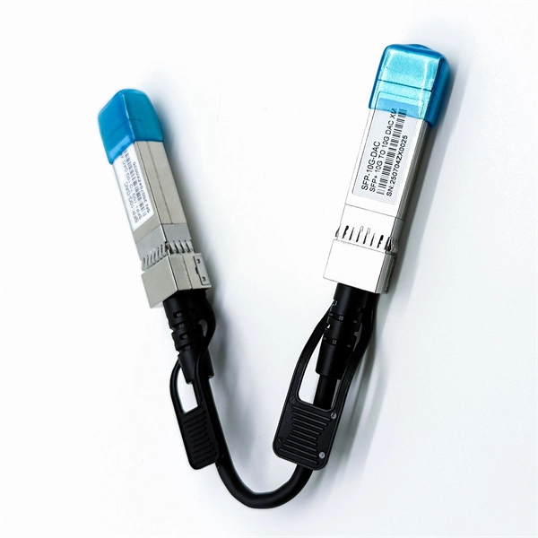
How about power communication optical cables
Power over Fiber (PoF) involves transmitting electrical power using optical fibers. CommScope solves these challenges with a complete range of powered fiber solutions designed for just the kind of high-demand powered devices that power smart networks in healthcare, hospitality, education, transportation and government environments, among others. That conversion can be done with a photovoltaic cell. A: OPGW (Optical Ground Wire) is a power transmission cable featuring dual functions on overhead lines. The power line protects (in lightning strikes) and the fiber for high-speed data communications. Widely used in overhead transmission lines, OPGW plays a crucial role in modern smart grids, telecom integration, and utility infrastructure. Utilities build fiber optic. This composite cable combines the distance and bandwidth capabilities of singlemode fiber with the power-carrying capability of 14-AWG copper conductors. by Jeanna Deese and Chris Rivas Power over Ethernet—it may be an old concept, but new applications continue to be identified that are redefining.
[PDF Version]
-
Does an optical power meter need to be calibrated after purchase
All test equipment must be calibrated on an annual basis. Calibration ensures that the test results you are measuring are indeed accurate. EXFO can help save both time and costs with an automated calibration test system that is designed for the verification of power meters, attenuators, sources and optical time-domain reflectometers (OTDRs). This application note demystifies how EXFO's IQS-12002 Optical Calibration System can guide. Below are general answers on how to operate, maintain, and calibrate an optical fiber ranger from the list of GAO Tek's optical power meters. Power On: Ensure the device is charged or properly connected to a power source. Select. n light source as shown below. Next press and hold the Mode Button until you hear a short. A send"'optical power meter is correctly calibrated when using a equivalent testing practices. For RF sensors, address mismatch uncertainty; for optical.
[PDF Version]
-
Construction site secondary power distribution box with 4 circuits
Electric power distribution systems are designed to serve their customers with reliable and high-quality power. The most common distribution system consists of simple radial circuits (feeders) that can be ov.