-
Function of the small busbar in the central power switch
The bus bar is a metal strip that distributes electrical current to the individual circuit breakers. In most assemblies you will find horizontal main bars, vertical risers, neutral and equipment-ground buses, and purpose-designed. What are Busbars, Bus Stabs, Circuit Spaces, Breaker Slots, Neutral Terminals, and Ground Terminals in an Electrical Panel or Load Center? Electric panels and load centers in residential and commercial applications have some different setting for breaker installation ad load circuit distribution. They connect directly to the main power source and are designed to handle high current loads safely. Circuit Breakers act as protective devices within the panel.
-
Small busbar acceptance standards and procedures
This article details the comprehensive standards for installing and inspecting busbars, including support brackets, insulators, and bus duct systems. You'll learn essential guidelines and. For complete safety instructions and precautions, always refer to the test equipment instruction manual. This approach is applicable to all types of metal enclosed busbar. Check for physical damage/defects. Check the bus arrangement to ensure that it is consistent with the approved plans. Compliance with recognized quality standards ensures electrical safety, reliability, and regulatory acceptance, especially for telecom, data centers, and industrial electrical applications. Buyers often. IEC 61439 is a standard developed by the International Electrotechnical Commission (IEC) that covers design verification for low-voltage electrical products and assemblies. Main keywords for this article are Bus Bars and Bus Ducts Design Requirements, ANSI C37.
[PDF Version]
-
Protection level of busbar connectors
The International Electrotechnical Commission (IEC) sets out standardized testing procedures and benchmarks to ensure that busbar contact resistance remains within safe and acceptable limits. IEC standards are developed through international consensus and are used globally. The integrity of busbar joints is critical because. Busbars in power systems are the location where transmission lines, generation sources, and distribution loads converge. Because of this convergence, short circuits located on or near the busbar tend to have very high magnitude currents. The high magnitude fault currents require high-speed. Industry data shows that loose or improperly torqued busbar connections account for a significant percentage of electrical panel failures. Busbar distribution ensures these requirements are fully met. Performance criteria of. DEFINITIONS.
[PDF Version]
-

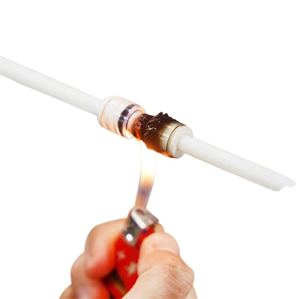
Busbar Connector Protection Box Usage
It is mainly used for insulation protection and safety protection of busbar connections in switchgear factories, power plants, and substations. In modern industrial electrical distribution systems, busbar systems serve as the backbone for power distribution, channeling electricity from main sources to various circuit protection devices and loads. The connection between molded case circuit breakers (MCCBs) and busbars represents a critical. The busbar joint protection box is made of radiation cross-linked polyolefin material. It has excellent physical, chemical and electrical properties. The high magnitude fault currents require high-speed. DEFINITIONS.
-
Standard Requirements for Busbar Connection Distance
The IEC standard for busbar clearance plays a critical role in the design and safety of electrical panels and power distribution systems. Key technical considerations include: 1. These clearances help prevent arcing, short circuits, and. Undersized busbar spacing is not a cosmetic defect. Dielectric tests, power frequency withstand for all voltages and impulse withstand for medium voltage, are specified in the standards. The design must pass these tests.
-
The function of the small busbar in the switch cabinet
A busbar is a metal bar, usually made of copper or aluminum, that carries electricity inside switchgear. It connects the incoming power to circuit breakers and outgoing circuits, helping power flow smoothly and evenly. Good busbar design helps prevent overheating and electrical. Busbars are the backbone of a low-voltage switchboard: rigid conductors that collect and distribute current safely between incoming devices and outgoing feeders. It connects. The use of busbar systems with their versatile rail-adaptable connection, switching and installation devices is an ideal and cost-effective electrotechnical enhancement of modern distribution boards thanks to their small footprint, modular design and quick assembly contacts. Small Busbar Room (Top of the Cabinet): Houses busbars that distribute electrical power to different sections.
[PDF Version]
-
Switch cabinet busbar installation
In North America, follow UL 891 construction and NEC Article 408 installation practices: use listed/approved hardware, lugs, or tap-off provisions intended for the bus. The matrix below helps engineers finalize material, arrangement, plating/insulation, and verification. The GRL busbar system makes distribution cabinet installation fast, flexible, and neat. At this stage, the supports have been installed in accordance with the installation plan. Ever wondered how busbars, the unsung heroes of electrical distribution, are processed and installed? This article delves into the intricate steps of busbar selection, preparation, and installation, ensuring efficient and safe power distribution. The application of these rules means strict compliance, not only with applicable regulations and standards, but also with manufacturers'. Bus bars play a crucial role in electrical distribution systems by providing a reliable and efficient way to conduct electricity within electrical panels.
[PDF Version]
-
Nordic Cable Tray and Busbar Manufacturer
We know cable management systems. Hilding Group consists of the three companies Nordic Wire Tray, Hiltec and Hilcon. Cable trays has an overall mission: to organize cables. In order to successfully meet the market's demands, high requirements and adaptations to various industries, a broad and well-thought-out range is required. Nordic Wire Tray's cable laying system consists of wire trays sold under the X-Tray. We specialize in manufacturing high-quality cable support systems. Our product range includes galvanized steel and acid-proof steel cable ladders, cable trays, wire mesh trays, lighting tracks, and aluminum-frame cable management systems, socket poles, and the unipro® lighting track system. Material Hybridization: Combinations of powder-coated metal, stainless steel, and solid wood or MDF are prevalent. New name, new look, same Nordic quality We continue to drive innovation in cable. Our cable management systems are designed to withstand the toughest conditions in C5-M environments, while delivering cost-effective and flexible solutions for platforms, vessels, and ports.
[PDF Version]
-

Mns switchgear busbar compartment height dimensions
Independent main busbar compartment is on the top part which is separated from the device compartment. In no event shall ABB be liable for direct, indirect, special, incidental, or consequential damages of any nature or kind arising from the use of this document, nor shall ABB be liable for incidental or consequential damages arising from use of any software. The MNS R frame is based on modular 2 mm thick still C sec-tions, pre-drilled at a pitch of 25 mm. The switchgear is pre set for easy extensions on both sides. The ends are designed to allow installation of future sections. With a rated voltage of up to 1000 V AC or 1500 V DC and a rated current of up to 6300 A, it offers exceptional performance and reliability. This together with the global service and support network established in over 30 manufacturing locations world wide ensures that the choice of MNS® will be the EC 61439 -1/2.
[PDF Version]
-
Reasons for switchgear busbar grounding
The ground bus inside metal-enclosed switchgear serves as more than a passive conductor. It determines whether personnel survive ground faults, whether protection relays operate correctly during switching transients, and whether equipment passes type testing. Grounding is one of the most crucial safety measures in electrical installations, and the bus bar. I know when you have a utilization voltage service transformer, you bond the neutral and ground buses at the service entrance equipment and from that point you are running 3P, 4W, plus an equipment ground through the whole system. The question I have is with primary switchgear used to distribute. This blog explains the difference between grounding in switchgear systems and earthing in switchgear system design, why they matter, and how they ensure reliable and safe power distribution. The neutral wire (white) and the equipment grounding conductor (EGC, bare or green) often terminate on bus bars that look. Abstract: System grounding considerations affect many aspects of an electrical system. Neutral and ground should only be connected together at one point in the electrical.
[PDF Version]