-
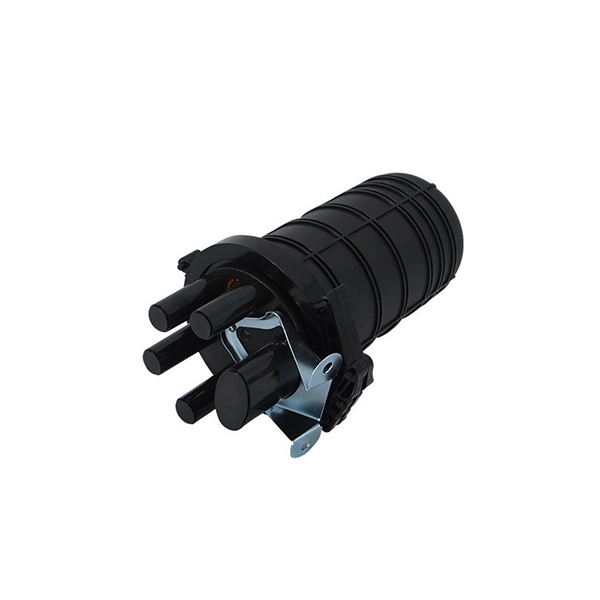
Fiber optic cable splicing techniques using heat shrink tubing
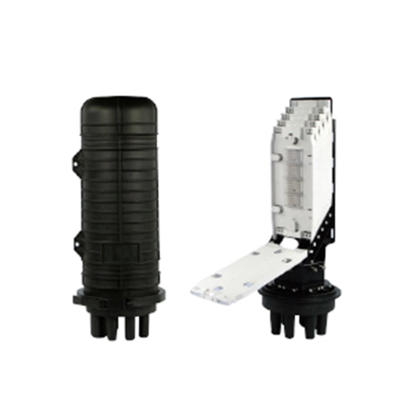
Carefully release each cable from splicer clamps. Slide shrink sleeve over exposed fiber and place in splicer's heating compartment; sleeve should cover each side roughly 3cm from joint. Consult the cable spec fication sheet for the cable you are installing. 1dB for fusion) and degrade over time in outdoor environments. A professional splice kit includes: Every splice starts with proper preparation: clean the work area, protect against wind, and. Single holed (preshrunk) ends eliminates improper fiber threading. Extended liner length prevents contact between the fiber and their backbone. Clear sleeve design permits easy centering. There are 7 procedures to perform in the splicing process; roughly in the following order: Procedures 2 and 3 will be performed twice; once for each of the two cables. Preparing to Use Heat Shrink Wrap: - Slide heat shrink wrap through one end of the fiber optic. A fiber optic heat shrink tube is used for reinforcing the splice connection.
[PDF Version]
-
The red light source of the optical power meter is not charging
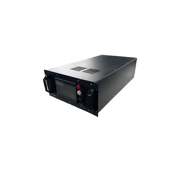
Recharge: Ensure the battery is fully charged before use. Use manufacturer-recommended batteries to ensure compatibility and performance. A general description is followed by explanations of how to operate the unit remotely via the serial RS232 connection. Turn on the optical power meter (OPM) using the power button. Select Wavelength: Use the wavelength selection feature to set the wavelength corresponding to the fiber optic system under test. However, should you have any questions or fi gistered users with a variety of information and services. Please allow us to serve you best by. 4 PM100D 1 General Information The PM100D Handheld Optical Power and Energy Meter is designed to measure the optical power of laser light or other monochromatic or near monochromatic light sources and the energy of pulsed light sources.
-

How to connect the cable tray ground wire
If an EGC cable is installed in or on a cable tray, it should be bonded to each or alternate cable tray sections via grounding clamps (this is not required by the NEC® but it is a desirable practice). Cable tray grounding wire is the safety connection that links your electrical system's cable tray to the ground. In addition to providing an electrical connection between the cable tray sections and the EGC, the. There are three wiring options for providing an EGC in a cable tray wiring system: An EGC conductor in or on the cable tray. Each multi-conductor cable with its individual EGC conductor.
-
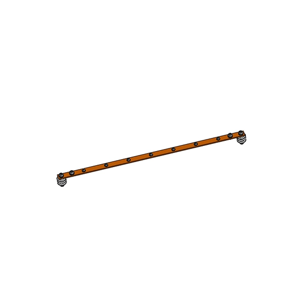
The function of the light guide bar light source module
Through the light diffusion structures on the incidence surface of the light guide bar and the full-reflection action of the light inside the light guide bar, the light guide bar can provide illumination with uniform brightness; and moreover, the utilization rate of. Through the light diffusion structures on the incidence surface of the light guide bar and the full-reflection action of the light inside the light guide bar, the light guide bar can provide illumination with uniform brightness; and moreover, the utilization rate of. The invention discloses a light guide bar and a light source module adopting the same. On a cross-sectional plane of the light guiding bar, there is a first line interval on the upper surface. A second line interval, a third line interval and a. Modern light guides are used for the transportation of light signals from a circuit-board-mounted LED via a particular route to a defined light-emitting surface, with minimal loss and blurring effect. They are used to illuminate areas that are too small or too hazardous to permit the installation of a light bulb.
[PDF Version]
-
Can a stable light source be used to measure light modules
A stable light source is very important to achieve usable measurement information, and also to ensure measurement repeatability. Over a period of time, any kind of light source will exhibit changes in spectral power output. Such changes comprise long- and short-term. Colour measurement is not only applicable to LED light sources, displays or other light emitting objects. Colorimeters or spectrometers can also be used for measuring the colour of objects that do not emit light themselves. In such conditions, a proper light source must be used to illuminate the. Expandable and compatible with DIMENSION's ALPHA and OMEGA universal optical test platforms. • 1CH, 2CH, or 4CH output available, each channel could be independently controlled. Wavelength and power can be customized. Image Credit: Leigh Prather/Shutterstock.
-
How to connect cable trays to the ground
If cable trays are to be used as grounding points, their connection points must be grounded using flexible jumpers with lugs of appropriate cross-sections. An EGC conductor in or on the cable tray. There are three wiring. Cable tray systems have become an essential component in the infrastructure of modern commercial buildings, smart offices, data centers, and various industrial facilities. These systems provide an efficient and adaptable solution for managing a wide range of cables, including power cables, control. When setting up electrical systems, grounding is a must. The Cable Tray Grounding Wire ensures everything runs safely and smoothly. In accordance with National Electrical Code (NEC) Article 392 “Cable trays” first determine the Maximum Fuse Ampere Rating or Circuit Breaker Ampere Trip Setting or Circuit Breaker Protective Relay Ampere Trip Setting for Ground-Fault Protection s the minimum.
[PDF Version]
-
Distribution Box Ground Resistance Test
The selective testing method uses one clamp and two stakes. It allows you to measure the ground resistance at specific parts of an installation, isolating the system to check or reference what's in place. Th.
-
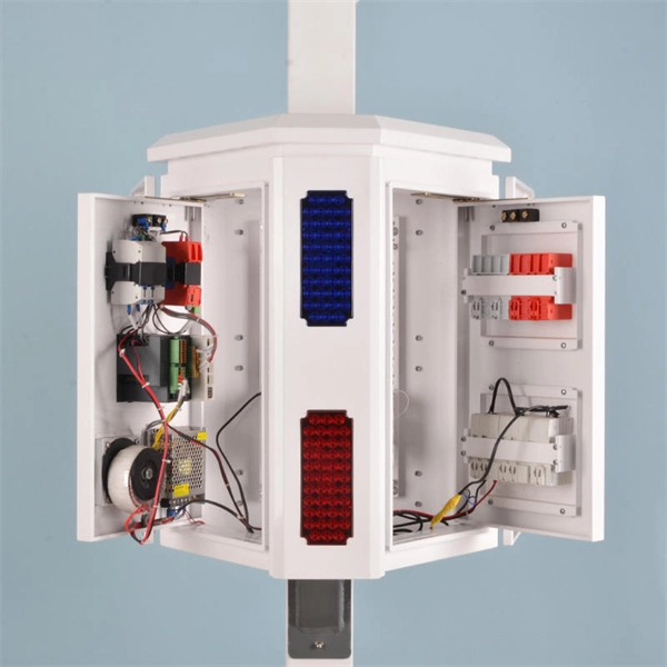
The ground wire can be seen in the distribution box
Open the distribution box and find the position marked with the grounding plate or PE letter. Connect the power ground wire Connect the ground wire in the power supply directly to the. The correct connection method of Distribution box grounding wire mainly includes the following steps: 1. This position is the connection point of the grounding wire in the. How to make proper & safe electrical ground wiring connections in the box: This article describes options for connecting a metal electrical box to the grounding conductor & connecting the grounding conductor to a fixture such as a ceiling light or ceiling fan. Understanding its role is essential for locating it safely. Preparation: First, you need to prepare some necessary tools, including grounding wire, grounding rod, voltmeter, insulating gloves and insulating tools. Make sure all tools are intact to prevent accidents during the grounding. On the US market, a 5. 26 mm 2 (10 AWG) ground wire must be used, and in all other markets a 6 mm 2 must be used.
[PDF Version]
-
Key Points for Installing Ground Wire in Household Distribution Boxes
In a system with metal boxes, the pigtail method is considered the most secure. In this arrangement, both the receptacle and metal box are grounded. Ground wires are spliced together and attached with a pi.
-
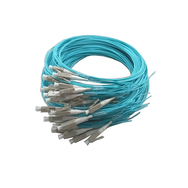
Price of fiber optic cable as ground anchor
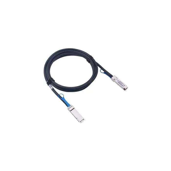
Prices vary based on the length of cable needed, installation method (aerial or underground), and labor rates in your area. Expect to pay $1 to $12 per linear foot, depending on project complexity and materials. Buying fiber optic installation services involves several cost components, with total price influenced by length, location, and access. Whether you're expanding your data center, connecting multiple buildings, or future-proofing your connectivity, accurate pricing information helps you budget effectively. UnitekFiber as a professional fiber optic cable supplier, we provide the high.
-
How high should the distribution box be to be ground level
Outdoor boxes need to be at least 3 feet above the ground. This keeps them safe from water and dirt. These heights follow rules like BS 7671 and IEC 60364-5-52. Check and fix the box often to prevent problems. Ensure safe placement: install in dry, accessible areas with good ventilation and at appropriate height (typically ~1. Practice good wiring: secure. The dimension for height of working space for equipment operating at 600 volts (V), nominal, or less to ground and likely to require examination, adjustment, servicing or maintenance while energized shall comply with the 110. 5 feet, the minimum workspace height shall be equal to the height of the equipment. Splices are to be made in boxes, like gutters / wireways.