-
Basement electrical distribution box grounding method
26 mm 2 (10 AWG) ground wire must be used, and in all other markets a 6 mm 2 must be used. On the US market, a 5. Each DISTRIBUTION BOX and controller must be grounded. Grounding of the units: Attach a ground wire from one of. Whether you're a seasoned pro or just starting out, this comprehensive guide will give you practical insights into proper grounding techniques, with a special focus on how selecting quality materials from a reliable building material supplier impacts your entire system's safety and longevity. NEC 2023 updates for basement and attic wiring requirements bring important changes that homeowners and contractors need to know. These updates aim to enhance safety and ensure that electrical systems in less commonly accessed spaces like basements and attics meet modern standards. This position is the connection point of the grounding wire in the. Abstract - The most common medium voltage electric dis-tribution system in the United States is multigrounded wye using a common neutral for both primary and secondary systems. NOTE: Some text links below go to applicable products at EMP Shield or Amazon. As an Amazon Associate, I earn from qualifying purchases.
[PDF Version]
-

Neutral wire connection method in the distribution box
Neutral (N) Wire Connection: For 1P circuit breakers, designed to control only the live wire, the neutral (N) wire bypasses the breaker and is directly connected to the neutral busbar. It then supplies the neutral current to individual circuits. The wiring method of the neutral bar in the small power distribution unit mainly follows the following steps and principles: Position determination: In the small power distribution unit, the neutral bar is usually located on the left side and installed on an insulated base to ensure safety. These two conductors serve fundamentally different safety functions, even though they may sometimes connect. The connecting wires in water tight electrical box should be insulated and the joints should not be loose. There should be no exposed live parts in waterproof cable box. Ground faults occur when a hot wire touches a ground wire or metal box, creating a dangerous surge that trips.
[PDF Version]
-

Installation Method of Home Electrical Distribution Box Switches
Learn how to install a distribution box safely and correctly. Covers wiring, placement, standards, and expert tips for a compliant setup. A distribution box is the heart of any electrical system. It takes the.
-
Photovoltaic Power Generation Module Installation Method
This article walks you through the basics of PV system installation, focusing on the practical steps from mounting modules to connecting the inverter to the electrical grid, and emphasizes the importance of ongoing maintenance to optimize system performance. (hereinafter referred to as LONGi). Please abide by all safety precautions in this guide and local regulations. •Installation of. Installing photovoltaic (PV) systems is a key stride toward embracing renewable energy, which is crucial for reducing carbon footprints and fostering sustainable energy use. Starting with a detailed site assessment to evaluate solar potential and optimal setup, the process ensures efficiency and. Protective earth grounding of the individual photovoltaic modules is achieved by securing the modules to the SRS mounting system. This guide provides detailed instructions for the proper application of SIRIUS PV modules.
[PDF Version]
-
Cost of laying optical cables using the airflow method
Prices vary based on the length of cable needed, installation method (aerial or underground), and labor rates in your area. Expect to pay $1 to $12 per linear foot, depending on project complexity and materials. By decoupling the empty microduct installation from the fiber blowing process, network operators can achieve up to 70% reduction in initial capital expenditure. Buying fiber optic installation services involves several cost components, with total price influenced by length, location, and access. Mainly manual. A fiber optic cable is made up of ultra-thin strands, each capable of carrying huge amounts of data at the speed of light. These strands are as fine as a human hair and are engineered for high-performance data transmission.
-
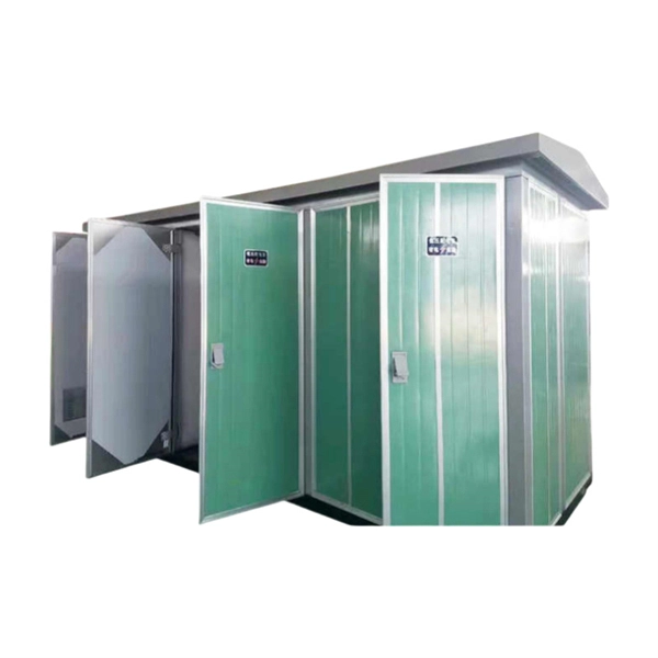
Installation Method of Cable Trays for Substations
Cable trays provide a strong mechanical support system while maintaining accessibility for inspection, maintenance, and future expansion. This article records the installation process of cable trays carried out in the substation, highlighting procedures, materials . This guide breaks down the whole process for the 35KV substation cable tray construction. We will focus on clarity, simple steps, and, most importantly, safety. My goal is to give you a simple, effective set of instructions. This ensures your 35KV substation cable tray construction meets all the. The installation of cable trays in substations plays a vital role in ensuring organized, safe, and efficient routing of power and control cables. This article. association representing the major electrical equipment manufac-turers in the U. The Cable Tray ng standards, performance standards, test standards and application in this document have been tested extens ompetent professional en completely installed, without damage either to conductors or. MP Husky Cable Trays are NEMA VE 2-2013 compliant. NEMA VE2 was developed by the NEMA Cable Tray Section, of which MP Husky is a charter member.
[PDF Version]
-
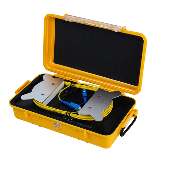
Method for laying 6-core armored optical cable
This guide provides a complete installation process for armored fiber optic cords, explaining each step from routing and pulling to stripping, cleaning, and testing. It also highlights key differences from standard fiber cables and important precautions to ensure safety and performance. The charter of the FOA was to promote professionalism in fiber optics through education, certification, and. Below is given the fiber optic cable installation method statement for performing the installation of optical fiber cabling system for any kind and size of project. The method covers the steps from receiving the materials on the installation site and cable pulling as per the approved shop drawings. Most systems use passive optical network (PON) architectures with signals going through splitters that allow up to 32 users to share one link and carry bidirectional signals. During installation, all curvatures should be smooth.
[PDF Version]
-
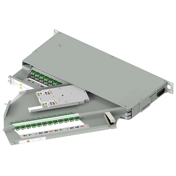
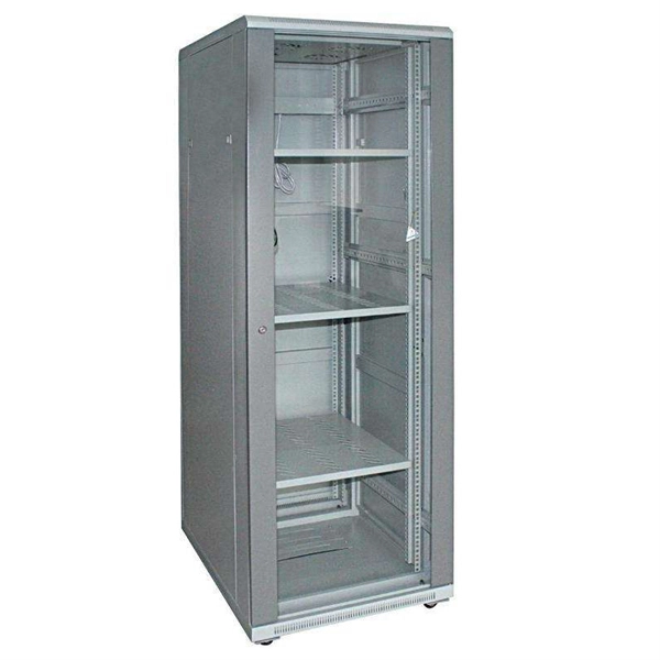
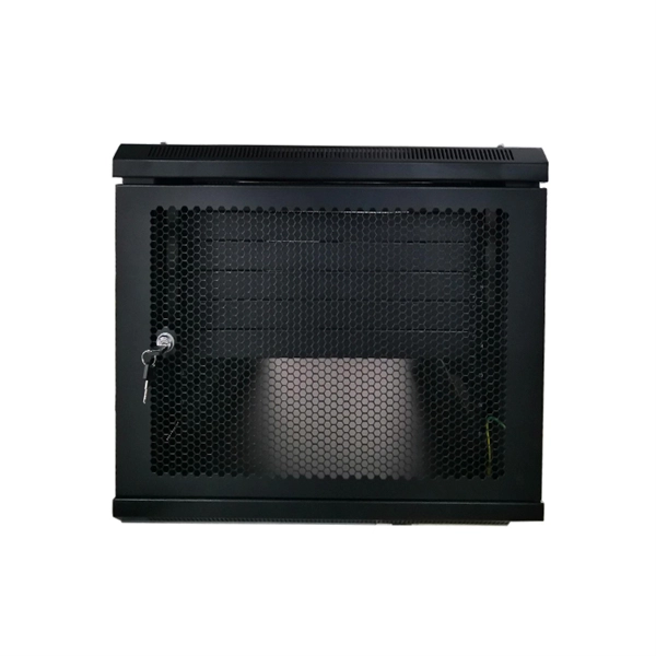
ODF rack fiber optic tray method
This blog provides a detailed overview of ODF trays, explaining their role in organizing fiber optic networks. It covers key features, installation steps, benefits of 19-inch rack mount models, and best practices for selection and maintenance. Whether you're building a central office, data center, or FTTx distribution network, understanding the right ODF. Opelink manufactures high-quality fiber optic distribution frames (ODF) designed for centralized fiber management in telecommunications facilities and data centers. In plain terms, an ODF is the enclosure where incoming fiber cables are routed, spliced, terminated and cross-connected to the active equipment or jumper/patchcords that feed the rest of a network. Adhering to standard 19-inch rack dimensions. View our full range of Fiber Optic Patch Panels to browse available configurations, including Rack Mount, Wall Mount, and High-Density ODF solutions. A Fiber Optic Patch Panel, also known as an Optical Distribution Frame (ODF) or fiber termination enclosure, is a centralized hardware unit designed.
[PDF Version]
-
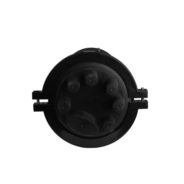
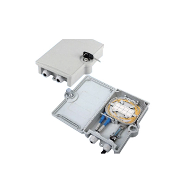
Fiber Optic Terminal Box Serial Connection Method
In network cabling, outdoor connections generally use fiber optic cables. When these optical fibers are installed or laid out, a Fiber Termination Box, or FTB, is used to distribute and protect the optical fiber link.