-
How thick is the angle iron for the base of a communication tower
Option A (All Q235 Mild Steel): To hold the weight of the antennas, the leg angles might need to be 200mm wide and 20mm thick. The total tower weight is 15 tons. Whether you're building a metal frame, reinforcing a structure, or designing custom supports, knowing the correct angle iron specs can make or. The most common steel grades used in mobile communication towers are Q235B (Mild Steel) for secondary bracing and Q345B/Q355B (High-Tensile Steel) for main structural legs. In international standards, these correspond to ASTM A36 and ASTM A572 Grade 50 respectively. For. Hot rolled ASTM A36 steel angle bar is the most widely used structural steel by the construction industry as its very economical cost. Structural mild A36 angles are manufactured by rolling pre-heated blooms into an angle shape. The tower transfers vertical and horizontal loads through a triangulated framework into the foundation, creating a highly efficient load path.
[PDF Version]
-
Calculation of Angle Iron for Cable Trays
Enter the applied point load or uniform load. Choose whether to include self weight. Press calculate and review stress, deflection, and capacity. Calculate horizontal, vertical, or compound cable tray offsets based on bend angle, offset distance, and available installation space. Measure this distance along the straight tray. Hubbell Take Off Support provides the contractor, engineer, end user a completed BOM, including all related products, counts, symbol legends and information required to price a project. Don't spend the many hours required to do counts and create BOMs for projects, rely on Hubbell's take off. Cable tray (or cable ladder) systems are a popular alternative to electrical conduit systems, as they have an outstanding record for dependable service, design flexibility and cost savings in commercial and industrial applications. A properly designed and installed cable tray system will provide. Stop Costly Cable Tray Installation Errors Now: Avoiding Mistakes in Instrumentation Cable Tray Installation: A Guide for EPC Projects Cable tray sizing in real EPC projects is not limited to simple area calculation.
[PDF Version]
-
Bending angle of vertical bend in cable tray
A box type cable tray vertical outside bend is a fitting used to change the direction of a cable tray system vertically, typically at a 90-degree angle, directing cables outward. How to calculate cable tray bends? Calculate the minimum required bend radius by multiplying the cable's outside diameter by its bending factor (e. Then, select a standard tray fitting (300mm, 450mm, etc. ) that matches or exceeds this value. Use this tool to estimate sloped section length, horizontal run requirement, cut marks, and installation feasibility. Measure this distance along the straight tray. 90° bend, Vertical Inner Bend, for all cable tray types of 50 mm side height. How to bend 90 degree of cable tray 3 line with the same distance :// • HOW TO BEND 90 DEGREE OF CABLE TRAY 3 LINE.
-
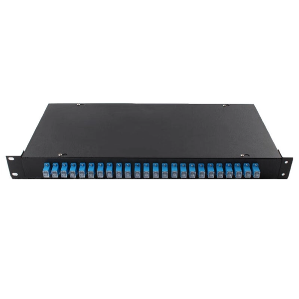
Fiber Optic Cable Tension Load Test Standard
This Applications Engineering Note (AEN 135) explains and recommends standard measurement methods for characterizing optical fiber system performance. FOA procedures, such as OFSTP-7 (single-mode) and OFSTP-14 (multimode), align with TIA and IEC standards. They describe how to set a '0 dB' reference, control mode power distribution, and use proper wavelengths. These procedures ensure you get consistent, repeatable results that meet international. d suppliers of electrical construction services. We're here to support your fiber network needs.
-

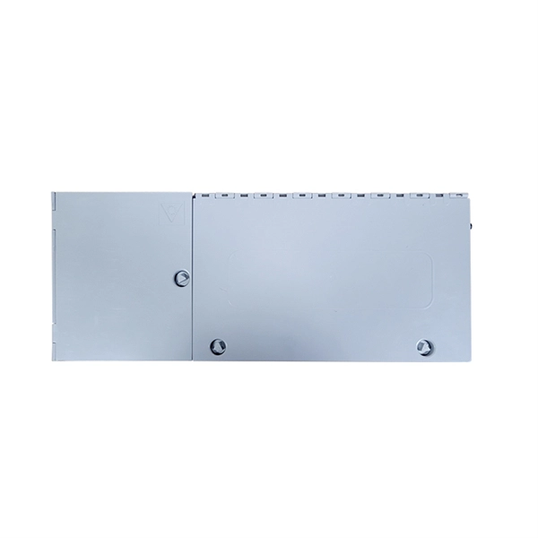
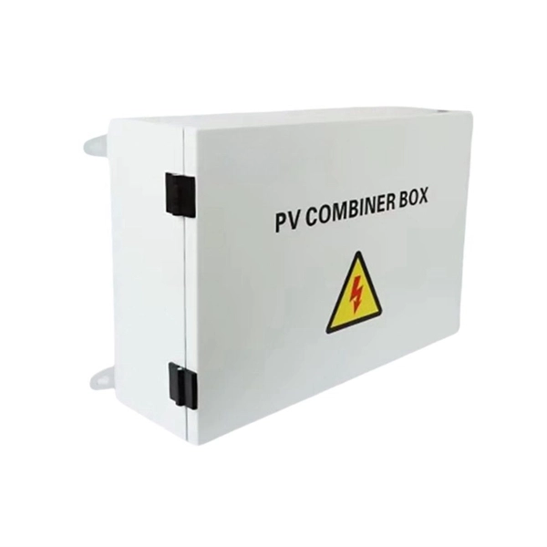
Check the load of the distribution box
Check the electrical load and ensure that the sensors do not exceed the 10 Amp maximum. Check the tightness of electrical connections along the. Professional electrical panel schedule tool for creating detailed load distributions, calculating circuit loads, balancing phases, and ensuring NEC compliance for electrical distribution panels. Check your panel often. Have a professional check it every 3 to 5 years to keep things safe. Do not make mistakes like adding breaker ratings wrong, using the wrong wire size, or missing hidden loads. Supporting 120/240V single-phase AC, this indoor circuit breaker panel provides a compact and organized solution for managing branch. The best distribution system is one that will, cost-effectively and safely, supply adequate electric service to both present and future probable loads—this section is intended to aid in selecting, designing and installing such a system.
[PDF Version]
-
Low-voltage busbar current carrying capacity standard
For busbar sizing, the primary references are IEC 61439 (for low-voltage switchgear and controlgear assemblies) and IEC 60287 (for current-carrying capacity of cables). IEC 61439 is a standard developed by the International Electrotechnical Commission (IEC) that covers design verification for low-voltage electrical products and assemblies. Special service conditions, for example in ships and in rail vehicles provided that the other relevant specific requirements are complied with. Current load capacity is the maximum value of the current flowing through the conductor in an unlimited period of time in certain conditions – it will.