-
High-Temperature Optical Cable Temperature Sensing
High-definition temperature sensing based on the natural Rayleigh backscatter in optical fiber delivers a virtually continuous line of temperature measurements with sub-millimeter spatial resolution. 1. Map temperat.
-
Working principle of thermal current relay protection device
The thermal relay working principle is that whenever a bimetallic strip in the thermal relay is heated up through a heating coil then it bends & makes normally open (NO) contacts. This article discusses an overview of a thermal relay – working with applications. What is a Thermal Relay? Thermal relay. A thermal relay is an essential component in electrical engineering, designed to protect electric motors and other electrical devices from overloads that might cause damage due to excessive current flow. Tips on connecting and competent configuration are given.
-

Inspection after changing the setting value of the relay protection device
The purpose is to inspect the insulation between the relay terminals and the ground. Use a megohmmeter (such as 500V DC). Check wiring & . Protection Relay Testing is the procedure used to verify the performance, accuracy, timing, and operational condition of protective relays installed in electrical systems. These relays monitor electrical parameters such as current, voltage, frequency, impedance, and phase angle. But when it's needed, it has to perform. Servicing protective relays per manufacturer and NETA recommendations ensures they work properly to prevent injury or extensive damage to your plant during. Low Tension (LT) protection relays protect electrical systems by finding abnormal conditions such as Ground faults.
-
Experiment on the Principle of Fiber Optic Pressure Sensing
Fiber optic pressure sensors operate based on the principle of light modulation in optical fibers. When pressure is applied to the sensing element, it changes the properties of the fiber, such as the refractive inde.
-
Ranking of companies with mature fiber optic sensing products
Companies like Schlumberger, OFS Fitel, AP Sensing, and Halliburton are leading the development of fiber-optic sensing technologies, especially in sectors like energy, oil and gas, and infrastructure. This section provides an overview for fiber optic sensors as well as their applications and principles. The market is estimated to exceed USD 2. Unlike traditional point sensors, DFOS systems use the optical fiber itself as the sensing element, providing. SLB (US), Halliburton (US), Yokogawa Electric Corporation (Japan), Weatherford (US), Luna Innovations Incorporated (US) are among the key players in the distributed fiber optic sensor market. Market participants have become more varied with their offerings, expanding their global reach through. The global market for Digital Fiber Optic Sensors was estimated to be worth US$ million in 2024 and is forecast to a readjusted size of US$ million by 2031 with a CAGR of %during the forecast period 2025-2031.
[PDF Version]
-
What is the SV interface of a relay protection device
IEC 61850 9-2, commonly referred to as SV, is the service that is used to exchange the raw power system samples from the station yard to the control house over Ethernet communication cables or network(s). SV operates on the same publish and subscribe model that GOOSE messages. SV-based process bus solutions from SEL feature intelligent merging units with built-in protective functions and use IEC standards to maximize flexibility and interoperability. Process bus systems based on SV and GOOSE protocols and the Precision Time Protocol (PTP) provide many benefits. A digital substation is an evolved form of a conventional electrical substation that leverages intelligent electronic devices (IEDs) in the place of analogue equipment to improve monitoring, control, and protection of power systems. We compare event. The two main interfaces are the Station bus and the Process bus (in Fig. 2, from IEC 61850-9, Figure 9, ). Latency accounts for processing delays, network queuing delays, and propagation delays in the channel. A simple Ethernet-based remote data acquisition system using IEC 61850 Sampled Values (SV) technologies is shown in the figure below.
[PDF Version]
-
10kV bus voltage exceeds the upper limit
The DC bus has exceeded the maximum value. Reduce the mechanical load and/or rate of deceleration. The DC bus overvoltage fault, also called a DC bus error or simply an overvoltage fault, is among the most common faults on an AC variable frequency drive. Because it's so common, some newer drives try to assist with locating the issue by providing more information about what the drive was doing. The DC bus voltage is too high. Thanks Engr Raja Haroon Rasheed Posted: 2020-07-03 01:39 PM. Last Modified:. Regenerative drives are built to handle excess energy, but when voltage levels spike beyond safe limits, your drive trips to protect itself. Maybe it only happens during high deceleration? Or maybe it's completely random? Either way, production stops, and downtime starts adding up fast. PV input voltage in Datasheet is not exceeded. If the measured voltage value is close to the maximum MPPT range threshold, it is recommended to reduce the number of photovoltaic panels in the corresponding sting.
[PDF Version]
-
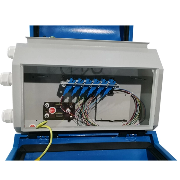
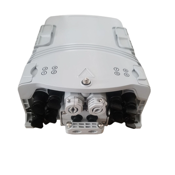
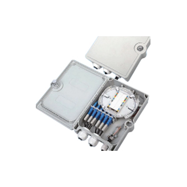
Fiber Optic Passive Device Standards
IEC 61753-1:2018+A1:2020 provides guidance for the drafting of performance standards for all passive fibre optic products. There are a number of ways of finding out more about cabling standards. You can also get catalogs and/or visit the websites of a number of cabling. A passive optical network (PON) is a fiber-optic telecommunications network that uses only unpowered devices to carry signals, as opposed to electronic equipment. In practice, PONs are typically used for the last mile between Internet service providers (ISP) and their customers. 1x32 splits were common in North America for G-PON architectures. As XGS-PON continues to be adopted, some service. Fiber optics standards are published by SAE, IEEE and others and cover a variety of topics relating to the testing and construction of fiber optics cables in a variety of different applications ranging from military and industrial use. In essence, a PON is a fiber-optic system that delivers data from a single source to multiple endpoints using only.
[PDF Version]