-
How to enable the optical module after plugging it into the optical port
Align the SFP module with the optical port and insert it horizontally, pressing firmly until the bottom of the module engages with the locking spring of the optical interface. Figure 1 SFP Optical Module Installation. The Cisco Small Business Series Switches allow you to plug in a Small Form-factor Pluggable (SFP) transceiver in their optical modules to connect fiber optic cables. Once the transceiver and fiber optic cable are plugged in properly in the switch optical module, you should be able to view the. This section describes how to install optical transceivers on the SFP or SFP+ ports and connect them to the ports of the peer device using optical fibers according to the network plan. The USG supports both 1 Gbit/s, 10 Gbit/s, and 40 Gbit/s optical modules. The LED will only light up when all connections are properly established and functioning correctly. The installation process can be taken by the following instructions.
[PDF Version]
-
Increase the light output power of the optical module
An optical amplifier is a device which receives some input signal light and generates an output signal with higher optical power. Typically, inputs and outputs are laser beams (very rarely other types of light beams), either propagating as Gaussian beams in free space or in a fiber. At the receiver end, the optical signals are reconverted into electrical. In this guide, we will explain what optical signal strength is, how to check it on Cisco IOS using the command line, and how to troubleshoot common light level issues. Assume the. This application note gives a short introduction to optical modules and the need of an optimized power tree in them and then concentrates on the use cases and benefits of four-switch and inverting buck-boost converters inside optical modules.
-
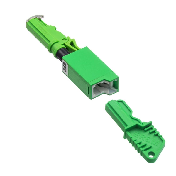
How to remove a loose pull ring from an optical module
Gently pull the module latch or release ring, depending on the module design. To use an SFP optical module, first confirm that the host port is SFP-type. Figure 1 SFP Optical Module Installation. However, with the right approach and careful handling, you can safely remove a transceiver stuck in a switch without causing damage to your network equipment. There are two primary reasons why an SFP module might become stuck in a port: The SFP is wedged in the cage: This can occur due to slight. To connect an optical cable to an SFP module, use the appropriate patch cord (e. Once connected, verify that the port activity indicator is on and run diagnostic commands to check the module status. After removing the fiber jumper, insert a clean dust cover over it to protect the end face of the module.
-
Is an optical module a chip
Optical module chips are semiconductor devices that enable high-speed data transmission in fiber optic networks. These components form the core of optical transceivers, converting electrical signals to optical signals (and vice versa) for telecommunications and data center. Optical modules and optical chips are two closely related but hierarchically distinct core concepts in optical communication systems. They differ fundamentally in functional positioning, structural composition, technical complexity, and application approach. Optical modules typically have an electrical interface on the side that connects to the inside of the system and an optical interface on the side that connects to the outside. The optical module serves as a crucial component in optical fiber communication systems, operating at the physical layer, which is the lowest layer in the OSI model. An. That is, metal medium communication represented by coaxial cables and network cables is gradually being replaced by optical fiber media.
[PDF Version]
-
Optical module receiving sensitivity is less than
Receive sensitivity defines the minimum optical power required to maintain an acceptable bit error rate (BER ≤ 1E-12) at specific data rates. It's a core parameter in optical transceiver specifications, indicating the module's capability to detect weak incoming signals. What Is BER? The bit error rate (BER) measures the data transmission precision within. In optical communication systems, sensitivity is a measure of how weak an input signal can get before the bit-error ratio (BER) exceeds some specified number. For example, SONET specifies that the BER must be 10 -10 or better. This level must fall within the receiver's power range.
-

How to connect the 10 Gigabit Ethernet cable to the fiber-to-electrical port module
A special 10G Copper RJ-45 Transceiver (10G-SFP-T) is required to connect the SFP+ port to RJ45. It allows connecting a server/storage side Cat6/7 cable to an SFP+ port transceiver. An SFP module (or optical transceiver) converts electrical signals from network devices (switches, routers) into optical signals for fiber transmission and vice versa. 1G/10G SFP+: Standard for Gigabit and 10 Gigabit Ethernet. These transceiver modules are hot-swappable input/output (I/O) devices that plug into 100BASE, 1000BASE and 10GBASE ports (for SFP+), which connect the module port with the fiber-optic or copper network. 4ft (30m) * using Cat6a/Cat7 or above cable for 10G connection in various applications. In this video, we'll guide you through building a high-speed 10G LAN by connecting two fiber switches. Finally, check the transmit (TX) and receive (RX) paths to ensure that signals are aligned.
[PDF Version]
-
How is the serial interface of the XFP optical module
The XFP 2-wire serial interface is used for serial ID, digital diagnostics, and certain control functions. It was defined by an industry group in 2002, along with its interface to other electrical components, which is called XFI. XFP modules can be installed or replaced in an Extreme Networks switch, I/O module, or router without powering off the system. All Extreme Networks XFP modules comply with. This Juniper Networks® XFP-10G-S compatible XFP transceiver provides 10GBase-SR throughput up to 300m over multi-mode fiber (MMF) using a wavelength of 850nm via an LC connector. It can operate at temperatures between 0 and 70C. The transceiver is compliant with CPRI, eCPRI. With these features, this 10G SFP+. ID systems defined for the GBIC and SFP transceivers. 12 document apply to Beta-and Production-level units only. Physical Medium Dependent (PMD) sublayer and baseband medium, type 10GBASE-S (short wavelength serial), 10GBASE-L (long wavelength serial), and.
[PDF Version]
-
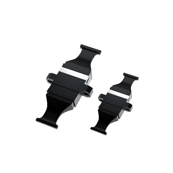
Optical Module Base Design
Optical module usually consists of a transmitter assembly (TOSA, containing a laser LD chip), a receiver assembly (ROSA, containing a photodetector PD chip), a driver circuit, an optoelectronic interface, a heat sink (some models), a housing, a pull ring and so on. Integrated circuits and reference designs help you create a smaller and faster optical module design used in high-bandwidth data communication applications. Whether you are creating a 100-Gbps or 400-Gbps, small form-factor pluggable (SFP) module, SFP+ transceiver, XFP module, CFP, X2/XENPAK module. Designing and producing these complex PCBs presents formidable challenges, requiring a convergence of disciplines—from high-frequency signal integrity and advanced thermal management to micron-level mechanical precision. These three laser diodes are described in more detail. contact us product page Copyright © 2024 MVSLINK. Critical Metrics: Signal integrity (insertion loss, return loss) and thermal management are the two.
[PDF Version]
-
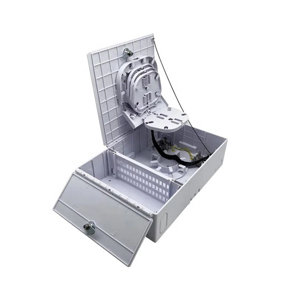
Symptoms of optical module failure
This is typically due to one of the following failures: hardware defect, poor seating, or incompatibility. The result here is a down port with no data flow. This could be that the link dropped periodically or the link was unstable. This article will help you understand various warning signs for common faults, suggest practical troubleshooting steps, and share preventive inspections and maintenance, so you can do your. While generally reliable, failures do occur, leading to frustrating downtime, performance degradation, and costly troubleshooting. This guide. An optical module is a critical component in modern optical communication systems, directly affecting transmission stability, network reliability, and operational efficiency. However, during installation and daily operation, various issues may arise.
-
Which end of the optical module receives light
At the receiving end, the module converts the light back into electrical signals for processing. Lasers are used for longer distances and higher speeds, while LEDs. It is processed by an internal driver chip, which drives a semiconductor Laser Diode (LD) or Light Emitting Diode (LED) to emit a modulated optical signal at the corresponding rate. The key components inside an optical module include: Laser Diode. The Transmitter Optical Sub Assembly (TOSA) is responsible for the emission of light. LD is suitable for long-distance, high-speed transmission, while LED is used for short-distance, low-speed applications.
-
How are the pins of the 2609B optical receiver module
With 900um-buffered single-mode fiber, without fiber connector. Internal current gain: 6 dB (typ. The 2609B is a packaged impedance-matched photodiode module with internal gain designed for use in optical broadband receivers in. The 2609B is a packaged impedance-matched photodiode module with internal gain designed for use in optical broadband receivers in fiber-optic networks. These are absolute stress ratings only. Functional operation of the device is not implied at these or any other conditions in excess of those given in the operational sections of the data sheet. Exposure to. no available.
-

Steps for replacing the CPU module of a relay protection device
Learn the essential steps for safely removing and reinstalling a PLC CPU module to prevent equipment damage, data loss, or safety hazards. Always consult the manufacturer's documentation for model-specific instructions. Incorrect wiring may result. 1. 1 INTRODUCTION TO THE UR The GE Universal Relay (UR) series is a new generation of digital, modular, and multifunction equipment that is easily incorporated into automation systems, at both the station and enterprise levels. The application software. Manual intended for personnel responsible for installing, commissioning and using VIP protection 400. The following steps outline best practices, but always consult the. This handbook covers the code of practice in protection circuitry including standard lead and device numbers, mode of connections at terminal strips, colour codes in multicore cables, dos and donts in execution.
[PDF Version]