-
Should the cable management rack be installed in the front or the back
Leave space for cable management —especially in the back. Ensure front-to-back airflow by leaving gaps or using filler panels. This method helps maintain neatness and accessibility within the rack while ensuring efficient airflow and ease of maintenance. Both overhead and under floor pathways should be designed to support the weight of cables in the initial installation and it should also facilitate the addition of future cables. With proper design and structured tools, it helps organize cables, ensure stable signal transmission, simplify maintenance, and improve overall system. Here are some best practices for rack placement: Implementing hot and cold aisle containment is a fundamental strategy for improving airflow and cooling efficiency. The racks should be positioned in a way that optimizes.
-
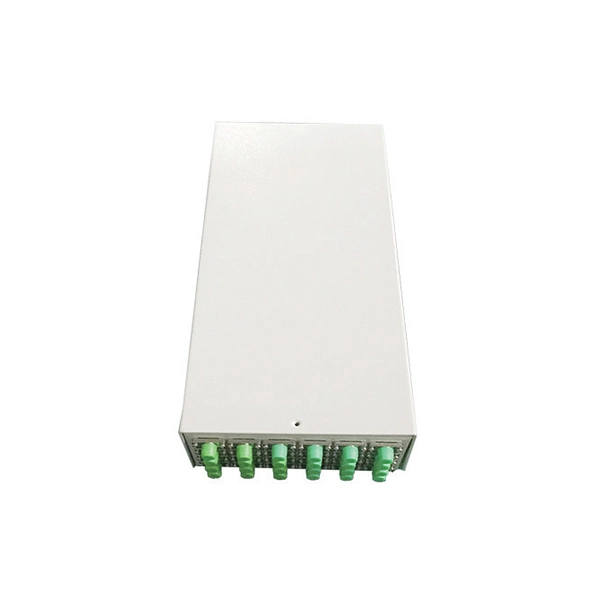
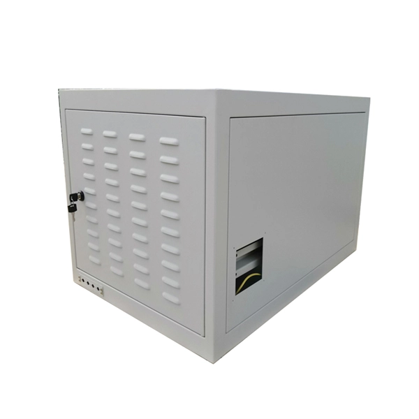
Spacing of the side of the distribution box
Side clearance: There should be a minimum of 30 inches of clearance from the sides of all electrical equipment, but in no case less than the width of the equipment itself. This is referred to as the side-to-side working space. In industrial power distribution systems, cable distribution boxes (also known as power distributor boxes, distribution electrical boxes, or electrical power distribution boxes) are the core hub of power transmission, branching, and protection. Its layout directly affects the efficiency of the. NEC Article 314 establishes requirements for the installation and use of electrical boxes, conduit bodies, fittings, and handhole enclosures. NEC Article 408. Boxes distribute low currents in an area equipped with 1 to 12 RJ 45 sockets. They centralise connections to ensure flexibility and that the installation is up to date.
[PDF Version]
-
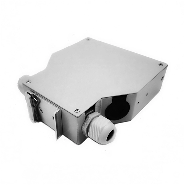
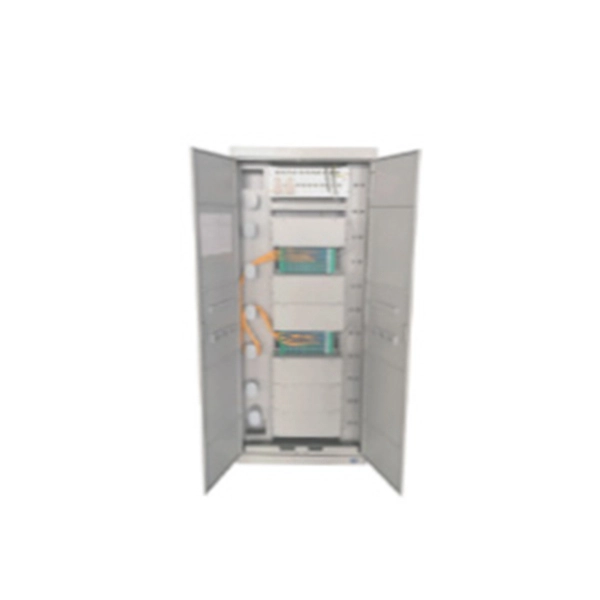
The power cable enters from the bottom of the distribution box
Cables can enter the structure from the floor (bottom entry) or from above (top entry. ) Distribution structures divide and send power to branch circuit protection devices and then to branch circuits to power downstream loads. Power. When installing a new overhead combination service for a residential service replacement we were told by the EI that we could not install our romex cables coming from under the house in a single 2" pipe approx. The scope of the article includes electrical requirements related to: Below is a complete overview. Once the box is securely in place, it's time to bring in the cables that will carry current from the main panel. Escape will cancel and close the window. Power from the utility company is typically delivered through three large conductors, which may enter the house overhead or underground. Overhead service. Fixed to a wall—This is a common approach for small electrical distribution boards. For bottom entry, the floor can incorporate a trench or false floor, which is often simpler since it provides.
[PDF Version]
-
Fixing bracket on the back of the distribution box
How to install the mounting bracket? Many engineers don't know how to install this accessory. With the latest design, it can be confusing. Mounting bracket is a flexible structure, which makes it easy to adjust or replace the electrical components. All the components, wires and connections are under the protective cover due to the same height. The BBT-HF telescoping bracket, used with the BBA and BBA-4 box mounting brackets, provides an extremely flexible, fast rough-in solution. more Charlie DIYte (CharlieDIYte) tagged products below. Make sure the walls are strong enough to bear the weight of the box and electrical equipment. Ground. Electrical box screw mounts broke, can it be fixed without tearing up wall? I was unplugging an appliance in the kitchen when the whole outlet pulled out of the wall. Second photo shows my temp.
-
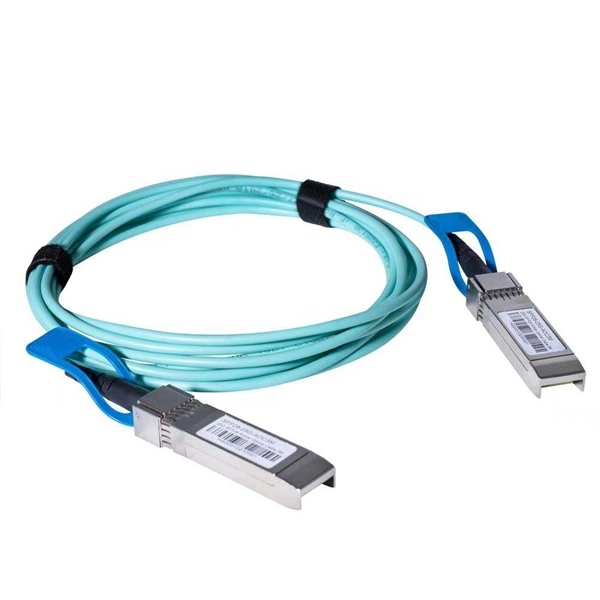
Power Grid Optical Cable Operation Level
Key OPGW testing methods include visual inspection, OTDR testing, optical power meter testing, continuity tests, and various mechanical and environmental tests. Each method targets a specific aspect of cable performance and safety. OPGW stands for Optical Ground Wire. These cables are used on high voltage power lines. I have managed many projects where I personally oversaw the testing process. I know that if testing. This specification defines the design, material, performance and test requirements for fibre optic cable to support the fibre optic telecommunication needs. How to calculate the required fault. ion infrastructure. Optical Ground Wire (OPGW)/Underground Fiber Optic Cable (UGFO) plays a crucial role in ensuring seamless data exchange, real-time monitoring, and reliable operati n of power systems. However, with increasing demands and multiple stakeholders involved in fiber usage, it became.
[PDF Version]
-
Requirements for Optical Module Circuit Boards
Since they are used to interconnect electronic devices, optical module PCBs are designed to meet several requirements, such as supporting high-speed data transmission, dissipating heat, and enabling hot-swapping. Optical module PCB design demands exceptional accuracy to ensure stable and. This guide serves as an in-depth resource for engineers, designers, and project managers involved in the development of optical module PCBs. 1 mm in thickness, with most designs comprising ≤12 layers. These materials lower energy loss and help high-frequency work better.
-
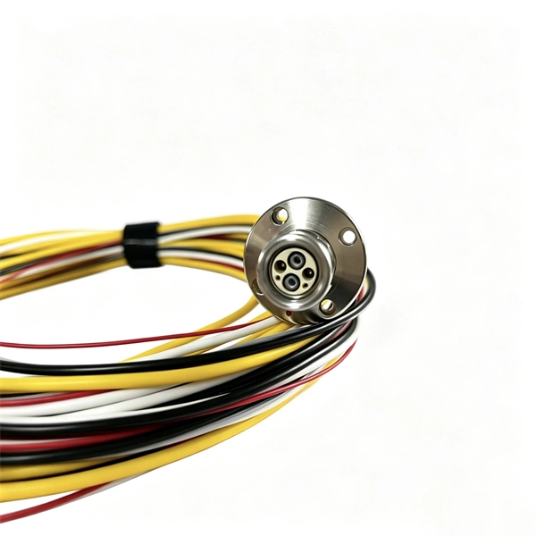
Control Principle of Fiber Optic Sensors
Fiber optic current sensors work by detecting changes in light as it interacts with a magnetic field created by an electrical current. This section provides a detailed look at fiber optic sensors. What Is a Sensor? Learn all about the principles, structures, and features of eight sensor types according to their detection principles. Radiation absorption creates electronic excited states that are trapped by localized defects for extended periods of. Brief theory of sensing principle, fabrication method, applications, advantages and disadvantages of the different fiber‐optic sensors, are addressed. Optical fiber sensors (OFSs) have emerged as essential tools in the monitoring of physical, chemical, and bio-medical parameters in harsh situations due to their high sensitivity, electromagnetic interference (EMI) immunity, and long-term stability.
[PDF Version]