-
What are the components of an optical guide driver module
The optical module is usually composed of Transmitter Optical Subassembly (TOSA, containing a laser LD Chip), Receiver Optical Subassembly (ROSA, containing a photodetector PD Chip), a driving circuit, and an optical and electrical interface. Its schematic is shown in Figure 1. The internal structure of an optical module is complex but can be divided into several main parts. It is the core device for connecting communication equipment with optical fibers. Operating at the physical layer of the OSI model, optical modules are core devices in optical. As an important part of fiber-optic communication, an optical module is a photoelectric converter which converts electrical signals into optical signals and vice versa. Composition of Optical Modules The optical module, known as Optical Transceiver in. The optical module serves as a crucial component in optical fiber communication systems, operating at the physical layer, which is the lowest layer in the OSI model.
[PDF Version]
-
How does the optical module test group perform its tests
Optical modules will go through strict testing and quality inspection procedures before shipment, such as material testing, parameter testing, aging testing, real machine testing, end-face testing, etc. In fiber optic networks, optical transceivers such as SFP, SFP+, QSFP28, and QSFP-DD play a vital role in converting electrical signals into optical signals and vice versa. Testing these modules ensures performance, compatibility, and long-term reliability in bandwidth-intensive environments like. QSFPTEK suppliers have strict transceiver testing and quality control processes, and each optical module is delivered with a complete testing process. Optical modules can realize end-to-end signal transmission, and it performs optical communication through optical fibers. However, due to the architectural differences between 4-channel and.
[PDF Version]
-
10 Gigabit Ethernet card optical module not connected to fiber optic cable
Troubleshooting SFP+ link issues in 10 GbE networks requires attention to module type, match of speed and wavelength, clean fiber connections, correct configuration, thermal management, and equipment compatibility. You can quickly resolve SFP+ Module connectivity issues by following a systematic optical transceivers troubleshooting process. Check for common connection problems, such as link failures or modules not recognized. Check compatibility between the optical module and switch Most switch brands have specific compatibility requirements. During network upgrades, many enterprise users encounter a common issue: after replacing 10G broadband lines or inserting 10G SFP+ optical modules, the switch still fails to operate at full 10G bandwidth or even fails to recognize the modules. We've listed the five most common ones. First of all, let's briefly recap what SFP and SFP+ stand for. SFPs – short for 'small form-factor pluggable' – are compact, hot-pluggable devices.
[PDF Version]
-
What s causing the optical module to have no light
Tip #5: How to deal with a “no light” issue? There are several reasons for “no light” issues: incompatible SFP module, incorrect connection, SFP module not powered on, or bad SFP. Incompatible SFP: Please check the compatibility of your optical transceiver with your. Tip #2: Why the LED of the switch slot does not light up after inserting the transceiver? It may cause by two reasons: compatibility issues and physical connection issues. If you have not inserted the SFP/SFP+/ XFP transceiver module into the switch slot correctly, it or link loss. The first thing. An optical module is a critical component in modern optical communication systems, directly affecting transmission stability, network reliability, and operational efficiency. However, during installation and daily operation, various issues may arise.
-

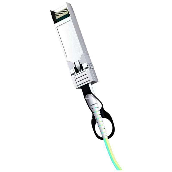
How to connect the SD signal in the 19 optical module
The unit accepts one SDI signal on a BNC connector and provides one optical output of this signal on an ST connector over single-mode cable with a 1310 nm wavelength. solution for virtually any conversion you could need. Mini Converters convert analog to digital, digital to analog, SDI to audio, audio to SDI, up, down and cross conversion, SDI distribution, and can even provide a sync generator for lockin all your video equipment to the same reference signal. These transceiver modules are hot-swappable input/output (I/O) devices that plug into 100BASE, 1000BASE and 10GBASE ports (for SFP+), which connect the module port with the fiber-optic or copper network. If the optical module is installed on a GE port, run the display interfaceGigabitEthernet x/x/x command to view port information when the optical module. When the optical module on an interface is faulty, you can run the display commands to view information about the optical module. The notices referring to your personal safety are highlighted in the manual by a safety alert symbol, notices referring only to property damage have no safety alert.
[PDF Version]
-
Optical Module Power Sensitivity
Receiver sensitivity is the lowest optical power level at which an optical receiver can successfully decode data with acceptable bit error rates (BER). It's a core parameter in optical transceiver specifications, indicating the module's capability to detect weak incoming signals. The transmitted optical power is related to the proportion of "1"s in the transmitted data signal; the more "1"s, the. Transmitter power characterizes the average optical power output from the laser under rated conditions, while receiver sensitivity indicates the minimum detectable power required to maintain a low bit error rate. An understanding of these concepts is pivotal to establishing an effective and efficient optical network.