-
Wiring of residual current circuit breaker in distribution box socket
In this video, I'll show you the complete wiring diagram of a home distribution board (DB). You'll learn how to connect the main circuit breaker (MCB), residual current device (RCD), and individual circuit breakers for lighting, sockets, and appliances. This guide provides a detailed, professional procedure for installing a Residual Current Circuit Breaker (RCCB)—a device essential for protecting people from the severe danger of electric shock. #dbbox #distribution #home #house. A distribution board or distribution box is where the main power supply is distributed to multiple loads. You will learn to build a safe, efficient, and professional electrical system today.
-
Complete Guide to Cutting Inner Bends of Cable Trays
This guide explains how to make 90° bends, vertical bends, tees, and offsets in wire mesh cable trays safely and professionally. Horizontal 90° Bend (Flat Bend) 2. Cross Bend (4-Way. OTHER THAN 90 ̊ JUNCTIONS Use this guide to learn the most effective installation practices when installing Cablofil tray. Each example of bends and tee's clearly illustrate proper tray cutting combined with recommended usage of Cablofil accessories. Oglaend System manufacture and deliver Multidiscipline modular bolted support systems, cable trays, cable ladders and accessories for complete installation and containment of Instrument, Electrical, Telecom, HVAC and Piping. Hubbell Wiring Device-Kellems and Hubbell Premise Wiring are divisions of Hubbell Incorporated, a U. headquartered manufacturer with over 130 years of supplying solutions for the electrical and data markets.
[PDF Version]
-

Principle of Residual Strain in Optical Cables
Residual elastic strains are local deformations resulting from residual stresses, which are stresses inside the fiber that persist even when no external forces are applied to the fiber. Residual elastic stresses and strains are important primarily because they perturb the fiber's refractive index. This study investigates the strain transfer mechanism for different types of fiber optic cables while embedded in concrete cubes, sustaining a boundary condition which features a displacement discontinuity. Understanding the strain transfer mechanism is required to interpret strain sensing results for fiber optic cables. INTRODUCTION Optical fibers are drawn with resin coatings that protect the glass. The residual stress profile arises from a thermal expansion mismatch of the constituent materials, the tension applied during fiber forming, and the thermal profile experienced by the fiber. non-destructive experimental procedure is presented which enables the determination of residual thermal stresses in optical fiber preforms. We carry out the measurement of the optical retardation using the traditional Senarmont compensation.
[PDF Version]
-
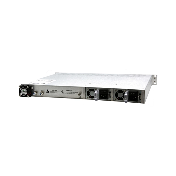
Metro-Grade OTN Router QSFP-DD Selection Guide
This guide provides a clear overview of 400G ZR QSFP-DD standards, specifications, and selection criteria for coherent pluggable optics in metro and long-haul networks. QSFP-DD ZR Coherent Optics presents a sea of change in the field of optical transportation architecture. The product supports 100Gbps transmission speeds in an. The QSFP-DD OLS is a pluggable open line system solution that can be directly hosted on a Cisco router. The Cisco® QSFP-DD Open Line System (QSFP-DD OLS) is a pluggable optical amplifier module that, together with the channel breakout options (described later), provides a simple yet powerful open. The 4. The DP01QS28-E20 and DP01QS28-E25 transceivers enhances the Routed Optical Networking solution by adding a 100G-only tuneable optic which be used across both. Quad Small Form-factor Pluggable Double Density (QSFP-DD) solution that fits into high-density switch and router client ports for optical interconnect links Powered by Greylock and Delphi DSP ASICs, and silicon photonic integrated circuits (PICs) for an optimized co-packaged design with 3D.
[PDF Version]
-

Relay protection voltage and current signals
A protection relay is a crucial component of electrical systems that safeguard infrastructure, employees, and equipment from electric problems and malfunctions. It. Reference Design to Measure AC Voltage and Current in Protection Relay With Delta-Sigma Chip Diagnostics (Rev. A) This high-accuracy analog front-end (AFE) reference design measures analog input performance and includes chip diagnostics to help identify power system failures using AC voltage and. The rectangular devices are test connection blocks, used for testing and isolation of instrument transformer circuits. In electrical engineering, a protective relay is a relay device designed to trip a circuit breaker when a fault is detected. ABB Type SAB Current Transformer CT's transform line current down to a signal level that is acceptable to the relay.
-
Low-voltage busbar current carrying capacity standard
For busbar sizing, the primary references are IEC 61439 (for low-voltage switchgear and controlgear assemblies) and IEC 60287 (for current-carrying capacity of cables). IEC 61439 is a standard developed by the International Electrotechnical Commission (IEC) that covers design verification for low-voltage electrical products and assemblies. Special service conditions, for example in ships and in rail vehicles provided that the other relevant specific requirements are complied with. Current load capacity is the maximum value of the current flowing through the conductor in an unlimited period of time in certain conditions – it will.
-
Working principle of thermal current relay protection device
The thermal relay working principle is that whenever a bimetallic strip in the thermal relay is heated up through a heating coil then it bends & makes normally open (NO) contacts. This article discusses an overview of a thermal relay – working with applications. What is a Thermal Relay? Thermal relay. A thermal relay is an essential component in electrical engineering, designed to protect electric motors and other electrical devices from overloads that might cause damage due to excessive current flow. Tips on connecting and competent configuration are given.
-
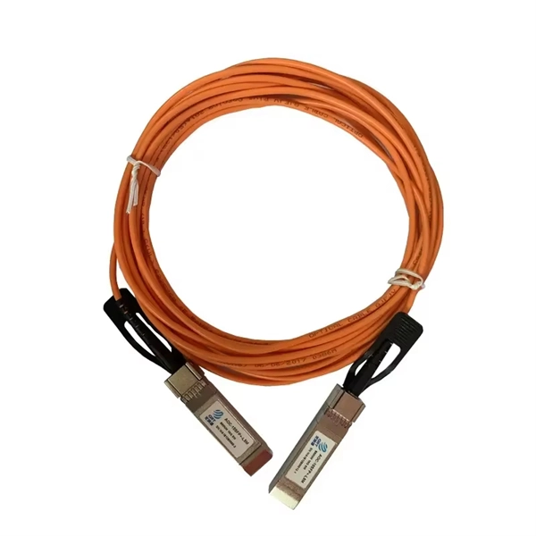
What are the components of an optical guide driver module
The optical module is usually composed of Transmitter Optical Subassembly (TOSA, containing a laser LD Chip), Receiver Optical Subassembly (ROSA, containing a photodetector PD Chip), a driving circuit, and an optical and electrical interface. Its schematic is shown in Figure 1. The internal structure of an optical module is complex but can be divided into several main parts. It is the core device for connecting communication equipment with optical fibers. Operating at the physical layer of the OSI model, optical modules are core devices in optical. As an important part of fiber-optic communication, an optical module is a photoelectric converter which converts electrical signals into optical signals and vice versa. Composition of Optical Modules The optical module, known as Optical Transceiver in. The optical module serves as a crucial component in optical fiber communication systems, operating at the physical layer, which is the lowest layer in the OSI model.
[PDF Version]