 Guide
Guide What is the acceptable db loss for single mode fiber?
To determine the acceptable dB loss for a specific single mode fiber installation, one must consider the power budget of the optical link. The power budget is the difference between the transmitter output
 Guide
Guide Fiber Loss Fault Analysis
For the Type A connector or the overall product design, the insertion loss at 1310 is significantly higher than the insertion loss at 1550, indicating a possible core-to-core alignment issue
 Guide
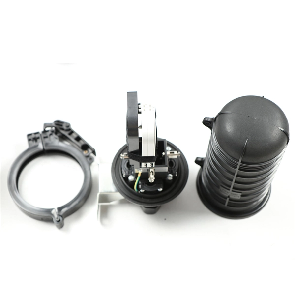
Guide 1310Nm Optical Fiber Cable Scscsm3Mpc – Aeliya Marine Tech
Optical Fiber Cable Scscsm3Mpc Insertion Loss: 1310Nm A: 0.11 B: 0.08 1550Nm A: 0.12 B: 0.09 Weight: 60 Gm
 Guide
Guide Recommendation ITU-T G.652 (08/2024)
This document outlines the specifications for a single-mode optical fiber and cable designed for use around the 1310 nm zero-dispersion wavelength, suitable for both the 1310 nm and 1550 nm regions,
 Guide
Guide Fiber Optic Cabling Loss Limits Explained – Trend Networks
Learn about fiber optic cabling loss limits & how to calculate them. Gain insights from experts on acceptable loss for cabling projects & explore the standards.
 Guide
Guide Fiber Performance Calculator
Calculate link or channel loss and determine the supported applications and max lengths for the configuration. The configuration and results can be exported as PDF.
 Guide
Guide Loss Budget (3)
Calculate fiber optic loss budgets with this tool, considering network hardware and dynamic range for optimal performance.
 Guide
Guide Fiber Loss Calculator | Lightem Technologies
Fiber Loss Calculator Download App From Google Play Fiber Optic Loss Calculator Select Fiber Type: MM 850nm (3.5dB/km) MM 1300nm (1.5dB/km) SM Indoor 1310nm (1.0dB/km) SM Outdoor 1310nm
 Guide
Guide Fiber Optic Loss Budget Calculator
Calculate your single-mode optical power budget of your transmitter & receiver set as well as passive devices with our tool
 Guide
Guide Fiber Splice Loss Calculator
Estimate fiber splice, connector, and cable attenuation losses. Compare totals against equipment power budget for reliability. Export results to reports and validate field designs quickly.