 Guide
Guide The essentials of LV/MV/HV substation bus overcurrent and
To isolate bus faults, all power source circuits connected to the bus are opened electrically by circuit breakers responding to relay action, by direct-acting trip devices on low-voltage
 Guide
Guide Busbar Differential Protection Scheme
Voltage Differential Protection: In this scheme, CTs are connected in series, and faults are detected based on voltage differences to avoid issues with
 Guide
Guide BUSBAR PROTECTION
The calculated current results in disconnection of the faulty busbar by the busbar differential protection. In the case of current transformers arranged on the line side, the fault must be disconnected by the
 Guide
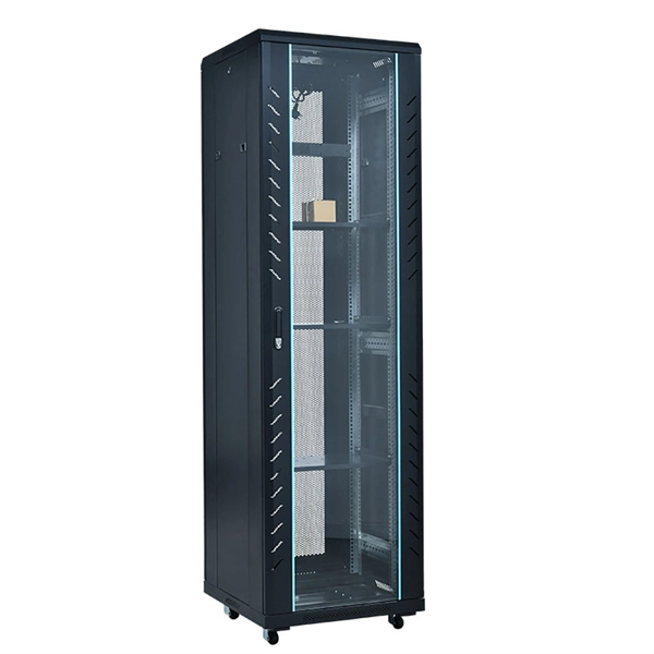
Guide Bus Protection Considerations for Various Bus Types
The tripping voltage threshold of a high-impedance differential element must be set high enough to ensure immunity against false operating current due to CT saturation, differing CT excitation
 Guide
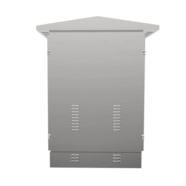
Guide Catalog Extract LV 10 · 10/2022
Our busbar systems for electrical installations offer a particularly easy way of fitting distribution systems with electrotechnical components. The modular design saves space, while quick assembly contacts
 Guide
Guide What is a PT Disconnection and Why is It Critical?
PT disconnection, a relatively common fault in electrical power production, occurs when the voltage transformer loses connection. Once the PT is disconnected and loses voltage, it critically affects the
 Guide
Guide 21955068-High-Low-Impedance-BusBar-Protection.ppt
The document discusses various techniques for bus protection, including: 1) Different bus arrangements used in transmission and distribution systems and their protection challenges. 2) Components of bus
 Guide
Guide Busbar and Multipurpose Differential Protection and Control
the current and voltage inputs are basic setting parameters of the protection relay. The binary input thresholds are selec able within the range 16...176 V DC by adjusting the binary input setting
 Guide
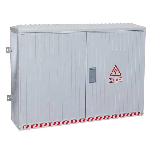
Guide Coordination and protection of busbar distribution
Design and production of a busbar distribution installation for industrial and commercial buildings must meet 3 main requirements: progressive upgradeability of the installation, simplicity and dependability.
 Guide
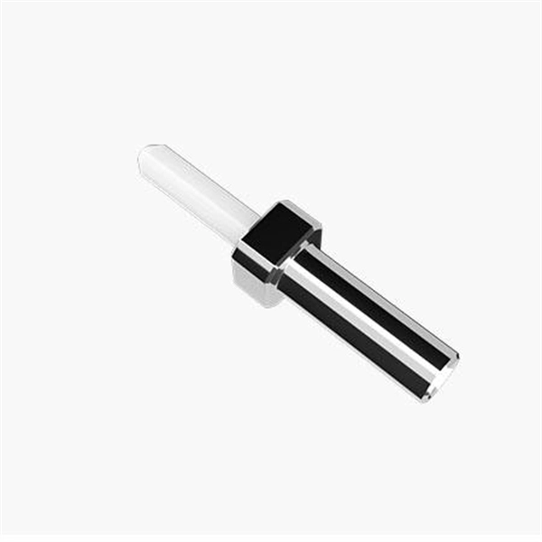
Guide Connecting a substation double 138 kV busbar with a disconnector
Disconnector in Bus coupler circuit should never be operated unless one of the busbars is dead completely. There are fast acting disconnectors available in the market that can be operated
 Guide
Guide SEL-487B-1 Bus Differential Relay Data Sheet
Busbar configuration information, as a function of the disconnect status, is readily available. Figure 6 depicts the response of the relay to the ZONE command, showing the terminals and bus zones
 Guide
Guide Bus Protection Theory
These requirements are necessary to keep the level of error voltage as low as possible to prevent maloperation of the relay. Making modifications to an existing bus protection scheme, such as adding