 Guide
Guide 4Ch_4-20mA_0-10VDC_DIN_U-026
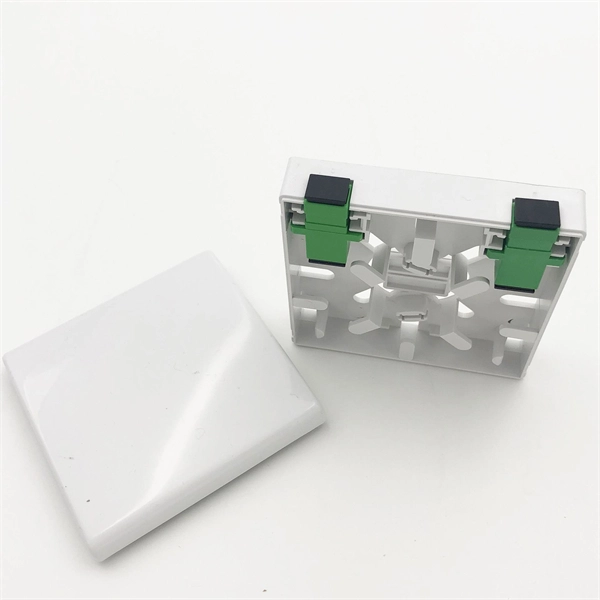
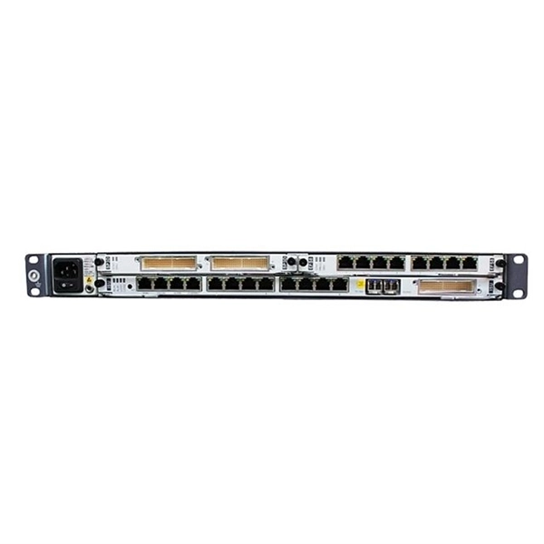
Analog Receiver Module The receiver module provides the optical-to-electrical interface between a fiber strand and four independent analog 4~20mA or 0~10VDC outputs. Each channel can be individually
 Guide
Guide Optical Communication Laboratory (ECC 17201)
In the experiment no. 1 (a), we have seen how analog signal can be transmitted and received using LED, fiber and detector. The same LED can be configured for the digital applications to transmit
 Guide
Guide Fiber Optic Analog and Digital Link (Set Up) : Remote Triggered Fiber
In this experiment we have used the ELVIS oscilloscope (channel 0 for input waveform and channel 1 for output wave form) and digital writer of the Prototyping board used as the switch to select either
 Guide
Guide Study of Optical Fiber Analog Links
2.1 Experimental Set-Up for FO Linear Intensity Modulation System The experimental set-up for studying a linear intensity modulation system is shown in the diagram below and is self explanatory.
 Guide
Guide DIGITAL COMMUNICATION LAB Setting up a fiber optic analog link
In this paper, we have compared OQPSK and DPSK bidirectional radio over fiber ROF systems, where an offset quadrature phase shift keying (OQPSK) or differential phase shift keying (DPSK) signals
 Guide
Guide RLH 4 Channel 4~20mA/0~10VDC Analog Data Fiber Link User
The Analog Data Fiber Link 4 Channel 4~20mA/0~10VDC User Guide provides detailed information on system installation, configuration, and troubleshooting. Includes system specifications, ordering
 Guide
Guide Experiment 1a : Fiber optic Analog Communication Link
This video describes setting up of analog communication link . Also explains the procedure to do the experiment.
 Guide
Guide Setting Up Fiber Optic Analog Link (Lab Experiment for
generator section. Observe the signal at SINE post on oscilloscope. Make the frequency at about 1 KHz using pot P2 and amplitude of about 1Vp-p using pot P1. Connect the function generator SINE post
 Guide
Guide Setting Up Fiber Optic Analog Link | PDF | Optical Fiber | Optics
The document describes how to set up a fiber optic analog link using equipment from a Link-A kit. It involves transmitting a 1 kHz, 2Vpp sine wave signal over a 1 meter fiber optic cable using an LED
 Guide
Guide DIGITAL COMMUNICATION LAB Setting up a fiber
In this paper, we have compared OQPSK and DPSK bidirectional radio over fiber ROF systems, where an offset quadrature phase shift keying (OQPSK) or
 Guide
Guide Optical Communication Lab Manual
Set up the 850 nm analog link using the 1m fiber. Drive a 1Vp-psinusoidal signal of 10 KHz with zero D.C. at P11 and observe the received signal P31 on the oscilloscope.