-

Optical module test power not adjusted too low
What does it mean if the transmitted power is too low? Low transmitted power can mean the connectors are dirty. Clean the connectors, check the module, and look at the fiber. If it still does not. Stable optical power is the foundation of every high-capacity optical transport system. Even minor deviations—whether too high, too low, or unstable—can impact signal integrity, trigger service alarms, or interrupt traffic on DWDM, OTN, or long-haul optical line systems. Because optical networks. The article Digital Diagnostic Function (DDM) For Optical Modules describes that DDM function can be used for real-time monitoring and fault location of the module's working status, in which the optical module's transmitting optical power and receiving optical power are the key parameters for. To test transmitted power in sfp optical modules, you use an optical power meter to get exact results. Many sfp modules also have DOM/DDM, which lets you see digital diagnostic monitoring data on network equipment. Built into modern SFP/SFP+/ SFP28 /QSFP family modules and standardized by SFF-8472, DDM/DOM exposes real-time values for the module's temperature, supply.
[PDF Version]
-
Analysis of Optical Module Sensitivity Issues
This guide provides a comprehensive overview of sensitivity analysis in optical design. It involves analyzing how the performance of an optical system varies in response to changes in its design parameters. For example, SONET specifies that the BER must be 10 -10 or better. By understanding the measurement standards, influencing factors, and application. It is often useful to analyze your tolerances in detail so that you can best understand where and why sensitivities exist in your optical system. In OpticStudio's tolerance analysis, you may save the tolerance results for each Monte Carlo file, or you may save each tolerance in the sensitivity.
-

How to enable the optical module after plugging it into the optical port
Align the SFP module with the optical port and insert it horizontally, pressing firmly until the bottom of the module engages with the locking spring of the optical interface. Figure 1 SFP Optical Module Installation. The Cisco Small Business Series Switches allow you to plug in a Small Form-factor Pluggable (SFP) transceiver in their optical modules to connect fiber optic cables. Once the transceiver and fiber optic cable are plugged in properly in the switch optical module, you should be able to view the. This section describes how to install optical transceivers on the SFP or SFP+ ports and connect them to the ports of the peer device using optical fibers according to the network plan. The USG supports both 1 Gbit/s, 10 Gbit/s, and 40 Gbit/s optical modules. The LED will only light up when all connections are properly established and functioning correctly. The installation process can be taken by the following instructions.
[PDF Version]
-
Ciscoh3C optical module compatibility
Link to compatibility matrix tool: Click here. com The current compatibility matrix allows users, typically Cisco customers and sales, to determine what transceivers are supported in Cisco hardware devices such as switches/routers and line cards/modules. Cisco does not support third party optics. For the guideline on third party components, see Section 6 of Cisco's Non-Entitlement Policy. For ONS Family optics product and compatibility information, please click here For High-Density Fiber Patch Panel, Simplex, MPO and Breakout Cables Portfolio Data. Optical modules transmit signals over optical fibers. Optical transmission features low loss and is fit for long distance transmission. The information is displayed in a. The following table shows the available transceiver modules for interface modules, MPUs, subcards, and devices.
[PDF Version]
-

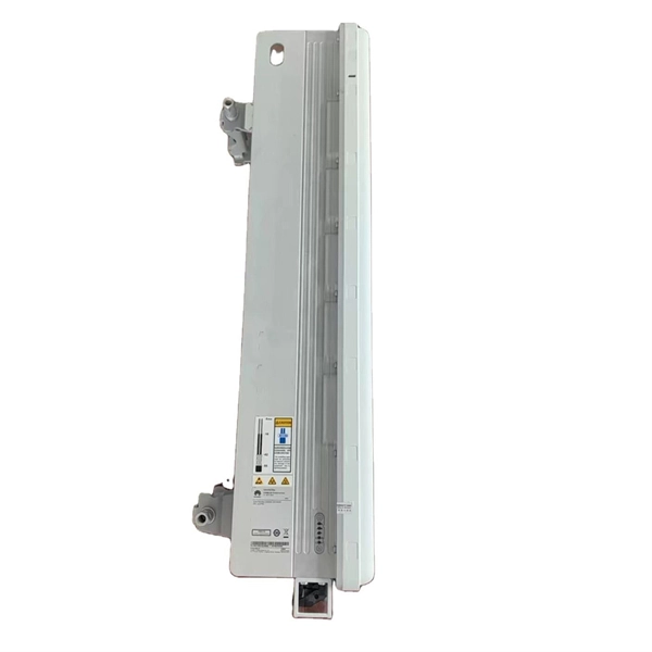
GPON optical module uplink
GPON is an alternative to Ethernet switching in campus networking. GPON replaces the traditional three-tier Ethernet design with a two-tier optic network which eliminates access and distribution Etherne.
-

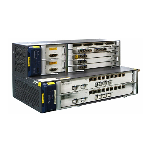
How to connect the SD signal in the 19 optical module
The unit accepts one SDI signal on a BNC connector and provides one optical output of this signal on an ST connector over single-mode cable with a 1310 nm wavelength. solution for virtually any conversion you could need. Mini Converters convert analog to digital, digital to analog, SDI to audio, audio to SDI, up, down and cross conversion, SDI distribution, and can even provide a sync generator for lockin all your video equipment to the same reference signal. These transceiver modules are hot-swappable input/output (I/O) devices that plug into 100BASE, 1000BASE and 10GBASE ports (for SFP+), which connect the module port with the fiber-optic or copper network. If the optical module is installed on a GE port, run the display interfaceGigabitEthernet x/x/x command to view port information when the optical module. When the optical module on an interface is faulty, you can run the display commands to view information about the optical module. The notices referring to your personal safety are highlighted in the manual by a safety alert symbol, notices referring only to property damage have no safety alert.
[PDF Version]
-
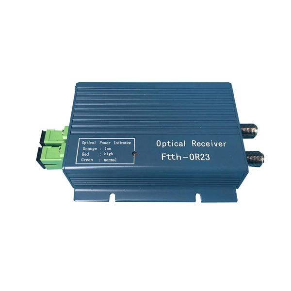
POB Parallel Optical Module
The POB series single-mode parallel optical transceiver module is designed for long-distance high-speed data communication and parallel optical interconnects in applications such as optical backplanes, server-to-storage array connections, and radar processing systems. ● Conform to GJB8120 General Specification for Semiconductor Optoelectronic Modules ● 10. It features a central wavelength of 850 nm, a single 3. 3 V power supply, and a single-channel transmission rate of.