-
Optical Module Lens Design
Looking to learn about optics and optical design? Learn the basics of optics needed to begin designing optical systems in this educational, online Fundamentals of Optics course co-created by E.
-
Is the 400G optical module made of silicon photonics
Based on Silicon Photonics (SiPh) technology, it integrates optical and electronic functions on a silicon substrate to enable 400Gbps high-speed interconnection in data centers. The advantages of 400G QSFP-DD are simplicity and compatibility. For 400G, the electrical signaling for both OSFP and QSFP-DD. 400G optical modules offer a range of technical advantages that make them well-suited for modern high-speed networks: High Bandwidth Density Each module supports 400 Gbps via 4×100Gbps or 8×50Gbps lanes, enabling dense connectivity without increasing port counts. These 4. By 2025, operators moved past 400G, with 800G becoming the mainstream, and early pilots pushing into 1. In early 2024, primary North American markets showed only 2. Switch ASICs now integrate HBM and extend fabrics up to 60 miles to. The Intel® Silicon Photonics 400G DR4+ (Data center Reach 4-lane with extended reach) QSFP-DD Optical Transceiver is a small form-factor, high speed, and low power consumption product, targeted for use in optical interconnects for data communications applications. The high bandwidth module supports.
[PDF Version]
-
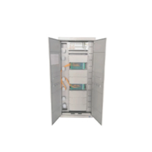
Function of optical module cage
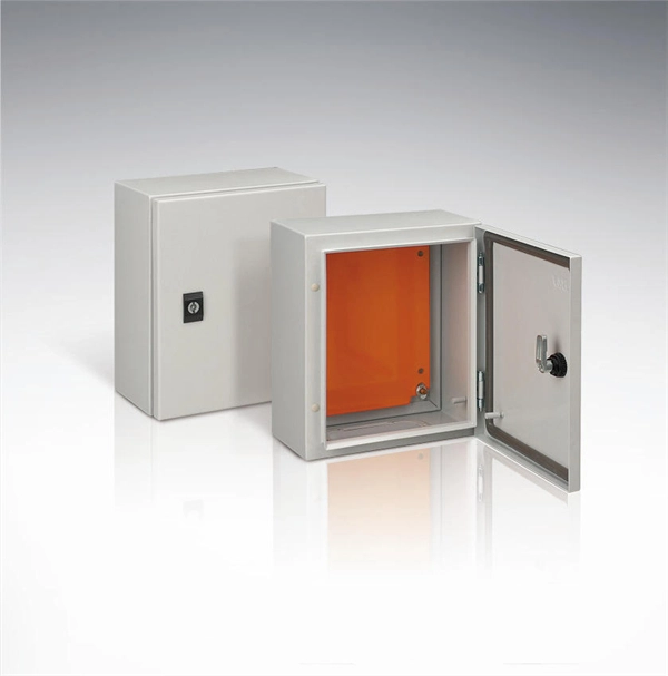
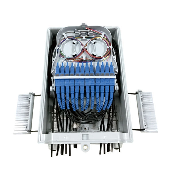
Simply put, a fiber optic cage (also commonly called an optical transceiver cage or cage assembly) is a precision metal housing designed to securely hold, align, and connect an optical transceiver module to a printed circuit board (PCB). Understanding what a fiber optic cage is and its role is essential for anyone designing, deploying, or maintaining robust optical infrastructure. This guide delves deep into the purpose, function, types, and importance of these fundamental components, highlighting their synergy with optical. An optical cage system uses four rigid steel rods to mount optical components along a common optical axis. Cage systems are available with center-to-center rod spacings of 16 mm, 30 mm, or 60 mm so as to accommodate Ø1/2", Ø1", or Ø2" optics, respectively. Thorlabs provides an extensive selection. Optical Cage Systems are used to create optical setups in a variety of prototyping or university research applications.
[PDF Version]
-
How to insert the Huijue optical module
Connect the XFP transceiver module to the network using an optical cable. After the optical cable is plugged into the transceiver, the LINK/ACT LED on the switch turns on. The following types of form. This section describes how to install an optical module. It is also prohibited to translate the document into other languages or use any or all parts of. P module is an input/output device that supports hot swapping.
-

What category of equipment does an optical module belong to
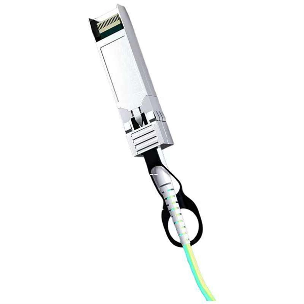
An optical module is a typically hot-pluggable optical transceiver used in high-bandwidth data communications applications. These modules typically consist of a transmitter, which converts electrical signals into a light signal, and a receiver, which converts the received signal back. Optical modules are compact devices that convert electrical signals into optical signals and vice versa. There are different types, like SFP and QSFP, for various uses. They work for short distances or fast data transfers.
-
GPON optical module uplink
GPON is an alternative to Ethernet switching in campus networking. GPON replaces the traditional three-tier Ethernet design with a two-tier optic network which eliminates access and distribution Etherne.
-

Optical module test power not adjusted too low
What does it mean if the transmitted power is too low? Low transmitted power can mean the connectors are dirty. Clean the connectors, check the module, and look at the fiber. If it still does not. Stable optical power is the foundation of every high-capacity optical transport system. Even minor deviations—whether too high, too low, or unstable—can impact signal integrity, trigger service alarms, or interrupt traffic on DWDM, OTN, or long-haul optical line systems. Because optical networks. The article Digital Diagnostic Function (DDM) For Optical Modules describes that DDM function can be used for real-time monitoring and fault location of the module's working status, in which the optical module's transmitting optical power and receiving optical power are the key parameters for. To test transmitted power in sfp optical modules, you use an optical power meter to get exact results. Many sfp modules also have DOM/DDM, which lets you see digital diagnostic monitoring data on network equipment. Built into modern SFP/SFP+/ SFP28 /QSFP family modules and standardized by SFF-8472, DDM/DOM exposes real-time values for the module's temperature, supply.
[PDF Version]
-
How to read the wavelength of a source optical module
In fiber optic networks, accurately identifying the wavelength of an optical transceiver module is essential for ensuring optimal network performance and reliability. One of the most effective and widely used methods is through the pull-tab color on transceiver modules. This simple visual system. That's where an Optical Spectrum Analyzer (OSA) comes in—a powerful instrument that measures the wavelength, power, and spectral characteristics of light. Think of it as a "microscope for light," revealing details invisible to the naked eye. We all know that CWDM has a total of 12 wavelengths, with a full band range of 1270-1610nm, with each wavelength interval of 20nm. SFP+: small form-factor pluggable plus, SFP with a higher rate. Considering that some newcomers to optical modules may not understand the letters on the optical module or the. Optical power, required for measuring source power, receiver power and, when used with a test source, loss or attenuation, is the most important parameter and is required for almost every fiber optic test.
[PDF Version]
-
How to print the optical module panel
You can print modules using a standard Print window, or the Print Preview window. A standard Print window is displayed that lets you specify which printer you want to use, what pages you want to. If an optical module on an interface is faulty, you can run the display commands to view information about the optical module. The fiber shuffle and MPO fan-out unit mechanically holds 14 and 10 passive. CommScope has collaborated with DYMO, a brand of RHINO Professional Labeling Tools and part of Newell Rubbermaid, to support the development and distribution of pre-formatted electronic templates, making the labeling of structured cabling systems easier and more efficient for installers., through the identification of the module information can be detected by the module and. LabVIEW tutorials on how to print front panel and block diagram of VI or application in LabVIEW. ✮ Facebook: / labview-advantage-209506362772803.
[PDF Version]
-
How does the optical module test group perform its tests
Optical modules will go through strict testing and quality inspection procedures before shipment, such as material testing, parameter testing, aging testing, real machine testing, end-face testing, etc. In fiber optic networks, optical transceivers such as SFP, SFP+, QSFP28, and QSFP-DD play a vital role in converting electrical signals into optical signals and vice versa. Testing these modules ensures performance, compatibility, and long-term reliability in bandwidth-intensive environments like. QSFPTEK suppliers have strict transceiver testing and quality control processes, and each optical module is delivered with a complete testing process. Optical modules can realize end-to-end signal transmission, and it performs optical communication through optical fibers. However, due to the architectural differences between 4-channel and.
[PDF Version]
-

Normal transmit and receive power of optical module
Transmit power is typically good when it is in the 6 dB range between -1 and -7 dBm. This guide provides average transmit and receive power ranges for transceiver modules. The TX (transmit) and RX (receive) power levels significantly affect everything from signal strength to transmission distances and the overall optical power. For network engineers working with fiber optics (SFP, SFP+, QSFP), understanding TX (Transmit) and RX (Receive) signal strength is critical.