-
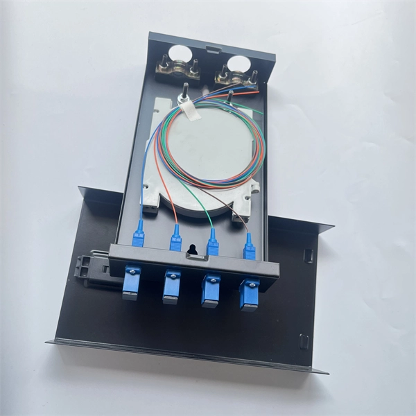
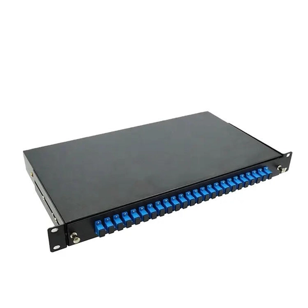
What are the testing methods for pigtail splicing
To test fibre splicer quality, begin by inspecting cleave angles and fibre cleanliness. Next, confirm arc calibration and alignment using the splicer's splice loss estimation. Follow up with OTDR or ILM testing to validate results. This guide covers everything: what fiber optic pigtails are, how they differ from patch cords, which connector and polish type to specify, how to choose between mechanical and fusion splicing, and the real-world applications where pigtails are the right call. The Contractor must utilize the correct equipment and testing techniques to gain acceptance, or the work cannot be approved. Either joining method must have three primary characteristics. The most efficient way to terminate a fiber run is by using a pigtail.
-
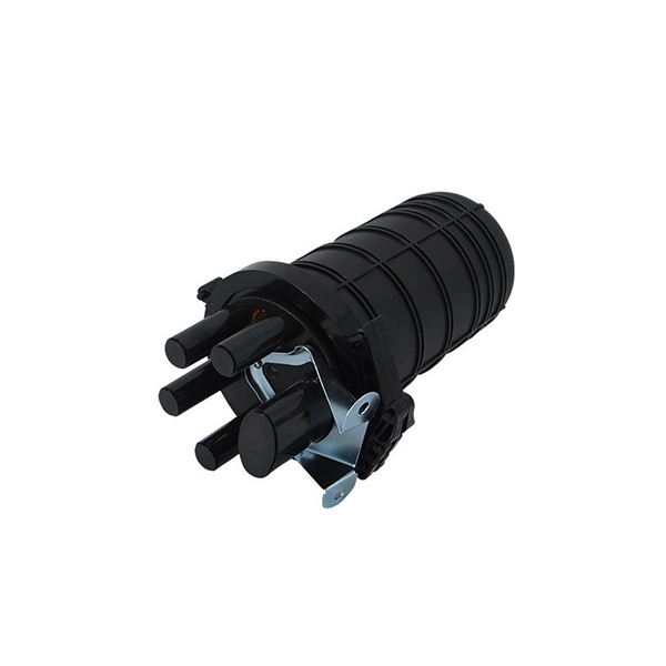
Outdoor Optical Cable Duct Laying Methods
Plan your outdoor fiber installation carefully by surveying the site, choosing the right cable type, and following FOA and OSP standards to ensure reliability. Select the best installation method—direct burial, aerial, conduit, or underwater—based on your environment and future. GL Fiber Optic Cable manufacturers will introduce three common laying methods for outdoor optical cables, namely: pipeline laying, direct burial laying and overhead laying. The following will explain the laying methods and requirements of these three laying methods in detail. Cable loops location identification. Match trench method with the correct underground fiber structure (GYTS, GYTA53, GYTY53, micro-duct). Duct fiber optic cables—often called “duct fiber”—are specialized optical cables engineered to be installed within pre-existing ducts (hollow tubes) rather than buried directly in soil or strung from poles. These ducts act as a protective pathway, shielding the fiber from environmental hazards. Corning Optical Communications cable specification sheets are available which list the maximum tensile load for various cable types.
[PDF Version]
-
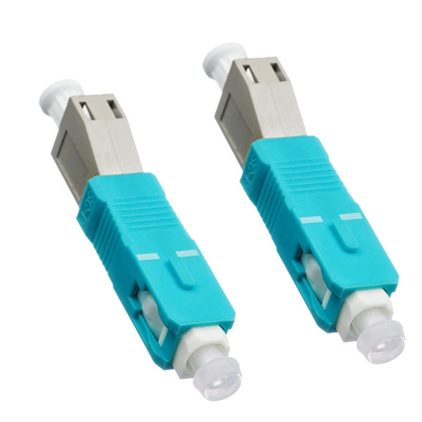
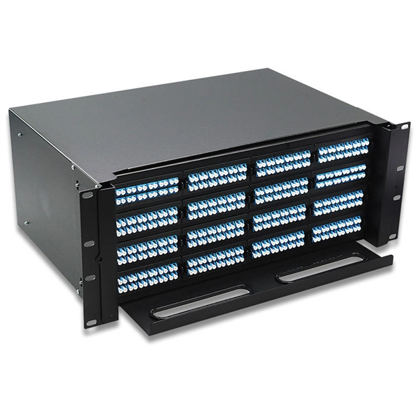
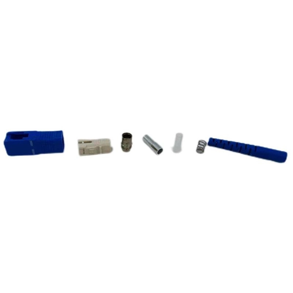
What are the splicing methods for fiber optic pigtails
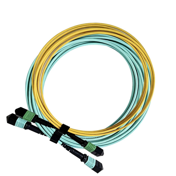
You have two methods: fusion splicing and mechanical splicing. The right choice depends on your performance requirements, budget, and the volume of splices you're performing. Fusion splicing uses a precision arc discharge between two electrode rods to heat and fuse the cleaved fiber. Get the wrong connector type, the wrong polish, or skip proper fusion splicing technique—and you're looking at elevated signal loss, increased back reflection, and a field termination that fails certification. This guide covers everything: what fiber optic pigtails are, how they differ from patch. The most efficient way to terminate a fiber run is by using a pigtail. Each fiber is marked “A” or “B”, or different colored connector boots are used to mark polarity. Similarly, 4, 6, 8, 12, 24, and 48 fiber. In this guide, we cover the basics of fiber optic splicing, how to perform splicing using two different methods, and finally some best practices to perform good fiber splicing. Either joining method must have three primary characteristics.
[PDF Version]
-
Low-voltage bus power supply methods include
The power supply, and more generally the different supplies, are provided by sources (mains supply, batteries, generator sets, etc. In a system with two incoming power lines, each line supplies part of the load. However, when a bus coupler cabinet is installed, it allows the system to. Eaton's Pow-R-Way III is a 600 V, totally enclosed, non-ventilated, sandwich bus design available with copper bus bars in ratings from 225–5000 A or with aluminum bus bars from 225–4000 A. Pow-R-Way III is available in outdoor feeder, indoor feeder, indoor plug-in and indoor sprinkler-proof. a minimum period of ten (10) years. Manufacturers listed above are not relieved from meeting the e specifications in their entirety. This. Busway solutions include these core elements: Insulation: This key component prevents electrical faults by separating conductors from one another and from the unit's housing.
[PDF Version]
-
Methods for measuring optocouplers using a multimeter
Testing the functionality of an optocoupler with a multimeter is critical for electronics enthusiasts and professionals. From basic circuit design to complex industrial systems, accurate optocoupler. Optocoupler is one type of ICs, It isolates input and output section by using optical technology this feature increase safety of circuit. Optocoupler has many part number, different part number has different output type so before checking it has to use part number to research with datasheet and. Testing for failure with a multimeter is only partially effective, whereas a dedicated optocoupler testing circuit provides clear results in just seconds. For related tutorials and step-by-step build guides, explore Circuit Digest's Electronic Circuits hub. Design considerations, including adequate spacing on PCBs for insulation, must be followed to ensure performance remains reliable and safe.
[PDF Version]
-
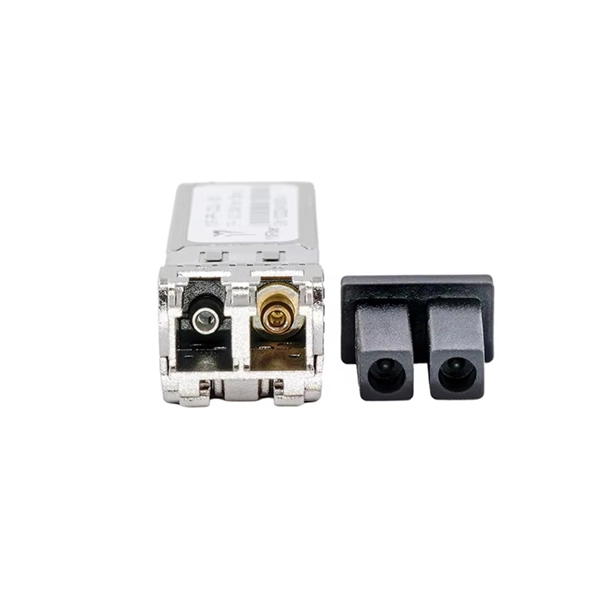
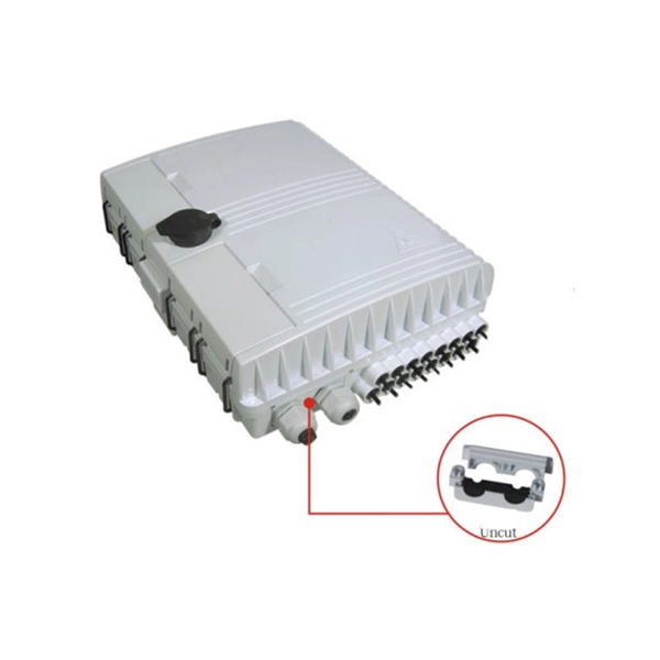
Methods for connecting fiber optic drop cables and patch cords
Get expert answers to 30 common questions about FTTH drop cable installation, including cable routing, tension, bending radius, SC/APC connector issues, fiber cleaning, and splicing methods. Ideal for fiber optic technicians and FTTH installers. Proper connection of fiber optic cables is essential to harness these benefits fully, as even minor errors can lead to significant performance issues like signal loss. This article will guide you through the necessary tools, materials, and methods on how to connect fiber optic cables effectively. This blog introduces installation methods of fiber drop cables for FTTH projects. This means: Drop cable becomes: System thinking replaces improvisation. 5 Selection vs Installation: Which Matters More? Both matter—but in different ways. Quick ODN improves both by: This reduces variation and error.
[PDF Version]
-
Rooftop Fiber Optic Cable Laying Methods and Prices
This guide covers the cost, price ranges, and main drivers behind fiber installation projects in the United States. The cost to lay fiber optic cable varies widely by route, terrain, and permit requirements. Assumptions: region, fiber type, trench method, and crew size; estimates reflect typical. With 19+ years of experience installing fiber-optic cables at over 20,000 locations, we've seen how prices vary based on cable type, project scope, and installation complexity. The installation type you choose and the layout of your property determine the total labor and materials needed for your project.
-
Methods for inspecting electricity meters and distribution boxes
Detailed procedures for electrical inspection, testing, diagnosis, and loss prevention, with links to critical safety information for electrical inspectors and electricians.
-

Aluminum Spectrometer External Testing
Spectrometers for Aluminium Testing, particularly Optical Emission Spectrometers (OES), are invaluable in achieving this. It ensures that each batch meets required specifications without compromising material integrity. The instrument takes advantage of modern CCD technology combined with the lates generation of readout electronics. The innovative optical system covers the entire usable wavelength range to enable selection of the best analytical wavelengths paired r numerous. Standard Test Method for Analysis of Aluminum and Aluminum Alloys by Inductively Coupled Plasma Atomic Emission Spectrometry (Performance Based Method) 5. Continuing this long tradition of excellence, the Thermo ScientificTM ARL iSparkTM 8860 Metal Analyzer is the trusted standard, which also integrates the latest innovatio cover your current and future needs in the. The energy dispersive X-ray fluorescence spectrometer (EDXRF) is widely used for quality control of aluminum alloys and acceptance inspections of recycled materials. However, analysis of light elements (particularly Mg) had been difficult until now due to the inadequate sensitivity and resolution.
[PDF Version]
-
How high should the distribution box be to be ground level
Outdoor boxes need to be at least 3 feet above the ground. This keeps them safe from water and dirt. These heights follow rules like BS 7671 and IEC 60364-5-52. Check and fix the box often to prevent problems. Ensure safe placement: install in dry, accessible areas with good ventilation and at appropriate height (typically ~1. Practice good wiring: secure. The dimension for height of working space for equipment operating at 600 volts (V), nominal, or less to ground and likely to require examination, adjustment, servicing or maintenance while energized shall comply with the 110. 5 feet, the minimum workspace height shall be equal to the height of the equipment. Splices are to be made in boxes, like gutters / wireways.
-
Connect the copper busbar in the computer room to the ground wire of the distribution box
Grounding electrode conductor (GEC) – wire connecting the panel to the ground rod. Drive a ground rod into the earth near the panel. This position is the connection point of the grounding wire in the. The Mesh-BN is the backbone of the bonding system, designed to ensure a uniform electrical potential across the entire data center. Now, let's. An electrical ground bus bar is a conductive bar made from materials like copper or aluminum, and it serves as the central point for connecting multiple grounding conductors in an electrical system. Grounding is one of the most crucial safety measures in electrical installations, and the bus bar. AI workloads, GPU clusters, and high-performance computing are pushing server rack power density to new extremes — from the historical 5-7 kW per rack to 20-40 kW or more. Our kits are available as one kit per rack to allow for ease of stocking and reordering.
[PDF Version]
-
How to connect cable trays to the ground
If cable trays are to be used as grounding points, their connection points must be grounded using flexible jumpers with lugs of appropriate cross-sections. An EGC conductor in or on the cable tray. There are three wiring. Cable tray systems have become an essential component in the infrastructure of modern commercial buildings, smart offices, data centers, and various industrial facilities. These systems provide an efficient and adaptable solution for managing a wide range of cables, including power cables, control. When setting up electrical systems, grounding is a must. The Cable Tray Grounding Wire ensures everything runs safely and smoothly. In accordance with National Electrical Code (NEC) Article 392 “Cable trays” first determine the Maximum Fuse Ampere Rating or Circuit Breaker Ampere Trip Setting or Circuit Breaker Protective Relay Ampere Trip Setting for Ground-Fault Protection s the minimum.
[PDF Version]