-

What does a 72-core optical cable look like
GYTA53 fiber cable consists of 250um fibers held in gel-filled PBT loose tubes, and wrapped around a phosphatized steel wire central strength member. A waterproof compound fills the loose tube, and the center of the cable core is a metal reinforced core. 72 core fiber optic cable should be selected by fiber standard, cable structure, jacket, tensile strength, installation route, drum length, testing, and quantity. single mode GYTA53 fiber optic cable and multimode. Fibertronics' Fiber Optic Distribution Cable is composed of high quality colored tight buffers, aramid yarn and a PVC outer jacket. Their small bend radius allows for fast installations and easy terminations within confined. Corning ribbon plenum cables are designed for use in plenum, riser and general purpose environments for intrabuilding backbone installations and for high-fiber-count data centers.
[PDF Version]
-
Optical cable channels are divided into
The light signal is divided into multiple channels with different frequencies and wavelengths, each transmitting a different data stream. In general, the fiber cable link system will be more secure if the fewer fiber cable segments. This region occupies a bandwidth of 95nm or 11THz! 8 cn cor where L is the fiber length, c is the speed of light, and ncor and nclad are the core and cladding refracitve indexes, respectively. Why not always use SMF? Optical phase information is lost in the detection process. What is a wavelength? What are optical wavelengths? What are nominal. In telecommunications, frequency-division multiplexing (FDM) is a technique by which the total bandwidth available in a communication medium is divided into a series of non-overlapping frequency bands, each of which is used to carry a separate signal. It essentially consists of a data transmitter, a transmission fiber (in some cases with built-in fiber amplifiers), and.
[PDF Version]
-

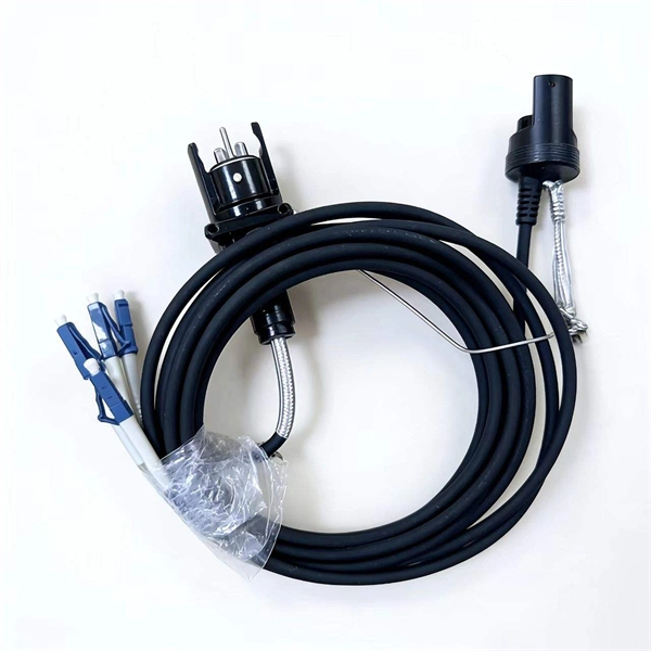
Single-mode port connected to multimode fiber optic cable
Single mode and multimode fiber cables are quite different when it comes to size, light source, signal, and so on. So, they definitely are not interchangeable, and compatibility issues can occur when you try to connect a single mode fiber optic connector to a multimode network. This is where fiber conversion comes in. Single-mode. To realize the short-range direct connection to the end B switch with the same port, the same 10GBASE-SR SFP+ module should be plugged into the end B switch port. What if end B is located in. It's possible because Multi-mode optical cables have a very wide fiber core – 62. Understanding the key differences between these two technologies is essential for IT professionals, business owners, and even homeowners looking to future-proof their network.
-
Installation of galvanized plastic cable trays
This guide covers the critical steps, from selecting the right electrical cable tray and performing accurate cable fill calculations to managing a safe cable pull through and ensuring all bonding and grounding requirements are met. Are you looking for a cost-effective and durable solution for organizing and protecting your cables? Look no further than cable tray galvanized. But before you lay the first tray or clamp down a single cable, you need a solid plan. This guide breaks down the process step by step. The selection of material and finish is a function of the environment in wh tant in a wide range of environments, and easily formable (Appendices II and III). The process described here takes a systematic approach to ensuring that cable tray installations meet safety, reliability, and project-specific needs while following to. Method Statement installation of Cable Trays and Ladders - Planning Engineer FZE.
[PDF Version]
-
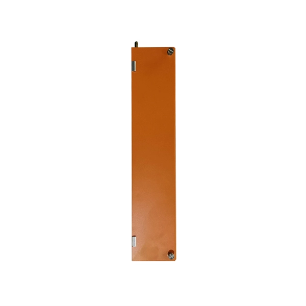
Fiber optic cable outer sheath representation
1 The outer cable jacket shall be marked with the manufacturer's name, date of manufacture, fiber count, fiber type, flame rating, listing symbol, and sequential length markings every two feet (e., “CORNING OPTICAL COMMUNICATIONS OPTICAL CABLE - MM/YY. XXXXX (feet. One important consideration when selecting indoor fiber optic cables is the outer sheath material and its fire prevention level. Each cable is single packed in a polybag with a test report that guarantees best performance in typical application scenarios like telecommunication, rack cabling, sensor technologies or indust Choosing the appropriate outer sheath material for fiber optic cables is crucial for ensuring the cable's durability, protection, and performance under specific environmental conditions. At the same time, it must have. 1. 1 The cable shall meet all requirements stated in this specification. Glass fiber and plastic fiber is fragile.
[PDF Version]
-
Stress on cable trays
Material selection: Cable trays are typically made from steel, aluminium, or fibreglass. Choose materials that meet or exceed industry standards (e. Is your cable tray system optimized for safety, dependability, space and cost savings? Cable tray (or cable ladder) systems are a popular alternative to electrical conduit systems, as they have an outstanding record for dependable service, design flexibility and cost savings in commercial and. This appendix provides the design criteria for seismic Category I cable trays and their supports. Seismic Category II cable trays and their supports are also designed utilizing the design criteria of this appendix. The selection of material and finish is a function of the environment in wh tant in a wide range. Cable trays are an essential part of modern electrical and communication infrastructure, providing critical support for power cables and wiring systems. The concept of “Cables in Free Air” for power distribution and control cables has been adopted primarily for economic reasons. Ensuring the structural stability of these systems is paramount to prevent accidents, downtime, and economic losses.
[PDF Version]