-
How to test the continuity of pigtail fiber
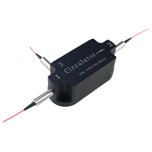
A visual fault locator (VFL) makes use of a visible spectrum laser light to test the continuity of the fiber and detect fault conditions. There are two reasons we may want to test bare fiber, by that we mean fiber that has not been terminated in connectors but is simply plain optical fiber, The first one is to ensure the fiber or cable being manufactured meets its specifications, as is done by every manufacturer. Fiber optic. The Optical Time Domain Reflectometer (OTDR) will be used to test splice loss and to conduct span analysis. An Optical Power Meter and Laser Light Source will be used to measure power loss on each completed ring or distribution span to verify continuity between fibers (no fibers incorrectly spliced. A visual check is often the first step when diagnosing a defective fiber pigtail. Continuity testing verifies that the fiber is intact and that light can pass through from one end to the other without any blockages. This comprehensive guide will equip you with the knowledge and skills to accurately assess the integrity of a pigtail, helping you identify issues.
[PDF Version]
-
Relay Protection Test Wiring Method
One approach to test the total protection system is to use primary injection techniques (see appendix H) that trigger protective relays and lockout relay, trip circuit breakers, and initiate annunciations and indications. If applicable, documentation is required detailing how verified protection segments overlap to ensure there is not a gap. The purpose of this Standard Work Practice (SWP) is to standardise and describe the method for testing of Ergon Energy protection relays for commissioning purposes. This SWP should be interpreted in conjunction with Standard for Substation Protection (V1. From a technician's perspective, master the unique skill of testing protection. When the transformer wiring type is Y/Y (Y0), the test wiring is very simple: when testing phase A, the tester IA is connected to the phase A of the high voltage side, and the tester IB is connected to the phase a of the low voltage side. After the neutral line of the high and low voltage sides is. Function: Use electronic components like transistors to perform switching. Applications: Frequency, undervoltage, and overcurrent protection.
[PDF Version]
-
Latest Standards for Relay Protection Withstand Voltage Test
IEC 60255-5 is the standard that defines insulation coordination for these devices — the test voltages, impulse withstand levels, and minimum insulation resistance values that every protection relay must meet. This article breaks down the standard's requirements with the specific clause numbers and. Abstract: Design tests for relays and relay systems that relate to the immunity of this equipment to radiated electromagnetic interference from transceivers are specified in this standard. Two types of tests are specified: the oscillatory (SWC) and. IEEE Standard for Relays, Relay Systems, and Control Devices used for Protection and Control of Electric Power Apparatus--Surge Withstand Capability (SWC) and Electrical Fast Transient (EFT) Requirements and Tests Abstract: Design tests for relays, relay systems, and control devices used for.
[PDF Version]
-
Fiber Optic Cable Tension Load Test Standard
This Applications Engineering Note (AEN 135) explains and recommends standard measurement methods for characterizing optical fiber system performance. FOA procedures, such as OFSTP-7 (single-mode) and OFSTP-14 (multimode), align with TIA and IEC standards. They describe how to set a '0 dB' reference, control mode power distribution, and use proper wavelengths. These procedures ensure you get consistent, repeatable results that meet international. d suppliers of electrical construction services. We're here to support your fiber network needs.
-
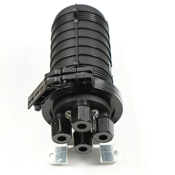
How to test a properly spliced optical cable
The most common methods for testing fiber optic splices are optical time-domain reflectometry (OTDR) and optical loss test set (OLTS). For every fiber optic cable plant, you will need to test for continuity, end-to-end loss and then troubleshoot the problems. If it's a long outside plant cable with intermediate splices, you will probably want to verify the individual splices with an OTDR also, since that's the only way to make. That's where splicing comes in—and knowing how to properly splice a fiber optic cable is a critical skill for any technician. Splicing allows you to restore or expand fiber networks while maintaining signal integrity. Fiber optic testing of a newly installed system not only verifies that the system meets its design requirements, but also creates a performance baseline for all future testing and troubleshooting of t at system.
[PDF Version]