-
Wired Channel for Relay Protection
With the addition of a line tuner, the CCVT (used for potential input to the protective relay) can be used to couple the PLC signal to the power line. Protection systems are used to isolate faulted parts of the system, protect the electric system from instability, and minimize equipment damage. Directional distance and overcurrent schemes, interfaced with communication equipment, send and receive logic-based information between relay te minals to determine if the fault is external or internal to the. Important benefits include limiting tripping to faulted line section, high-speed simultaneous clearing for all internal line faults, preventing overtripping on external faults, and reducing transmission line and station damage. Applications of the concepts to accepted transmission line-protection schemes are also presented.
-
The higher the optical power of the optical module the better
The optical power budget represents the maximum allowable signal loss in a fiber-optic link. It is calculated by subtracting the RX sensitivity from the TX power. The transmitted optical power of the optical module is an important parameter that affect the transmission distance of the optical module. The stronger the. In the world of enterprise and data center networking, Small Form-factor Pluggable (SFP) modules are the quiet workhorses that connect routers, switches, and optical fiber links.
-
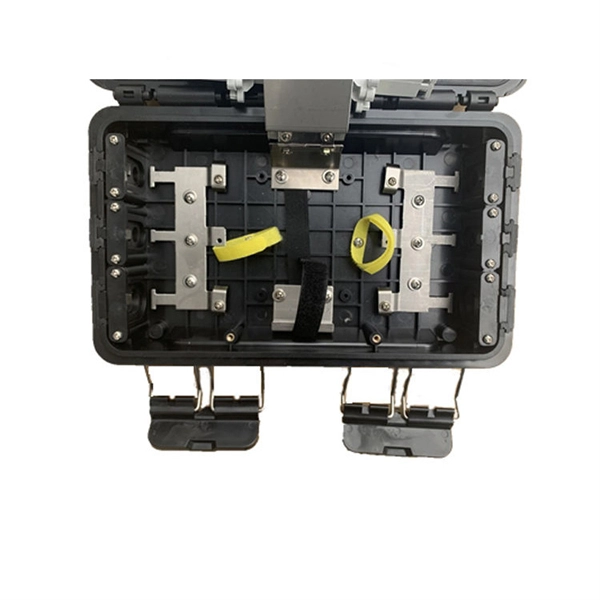
Optical Communication Module Coupling Technology
The main functionality is to provide a coupling between electro-optical components (e. laser diodes, photodiodes or silicon photonic chips) and optical fiber. Highly efficient coupling can directly improve communication quality, and using automatic alignment can significantly reduce the coupling-alignment difficulty. This chapter presents the design of a closed-loop. The HUBER+SUHNER Cube Optics optical coupling modules are revolutionizing the on-board optical interfaces. The FBT coupler is fabricated by fusing two or more optical fibers together and then tapering the fused region to create a coupling region. It provides state-of-the-art functions, services, and safeguards s (OCM to OCM or OCM to LM). 9B by 2029, fueled largely by AI data centers.
-
How are the pins of the 2609B optical receiver module
With 900um-buffered single-mode fiber, without fiber connector. Internal current gain: 6 dB (typ. The 2609B is a packaged impedance-matched photodiode module with internal gain designed for use in optical broadband receivers in. The 2609B is a packaged impedance-matched photodiode module with internal gain designed for use in optical broadband receivers in fiber-optic networks. These are absolute stress ratings only. Functional operation of the device is not implied at these or any other conditions in excess of those given in the operational sections of the data sheet. Exposure to. no available.
-
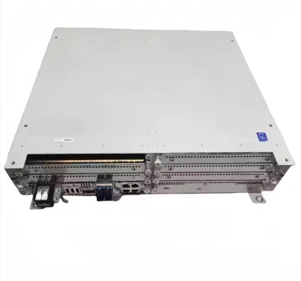
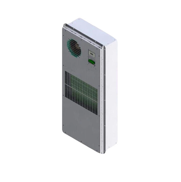
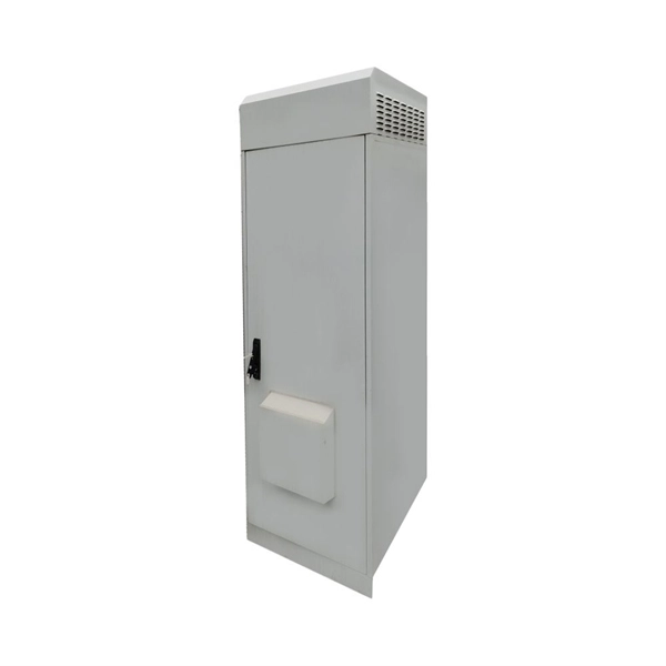
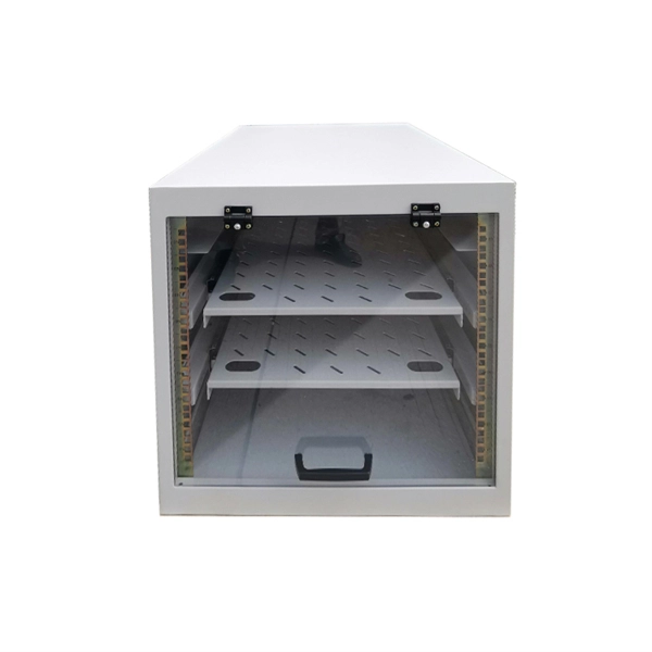
What is the network module for a low-voltage electrical cabinet
MNS is ABB's low-voltage switchgear and controlgear assembly for power distribution and motor control. The MNS design is verified in accordance with the latest IEC standards, IEC 61439 -1/-2 and IEC TR 61641. MNS switchgear assembly is of scalable design, enabling ABB to supply integrated solutions. From circuit breakers and buses to enclosures, panel boards, and switchboards, we offer a full range of safe, reliable solutions for low-voltage electrical distribution applications. Some links are removed, so that each (fused) distributor leaving a substation forms a branched open-ended radial system, as shown in Figure C4 In European countries the standard 3-phase 4-wire. By contrast, U. low-voltage electrical systems are divided into four clearly defined equipment types, each governed by its own UL or IEEE standard. These distinctions affect enclosure structure, breaker selection, busbar layout, safety clearances, and pricing logic. A collection of one or more of these.
[PDF Version]
-
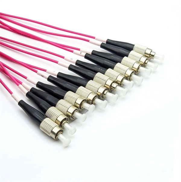
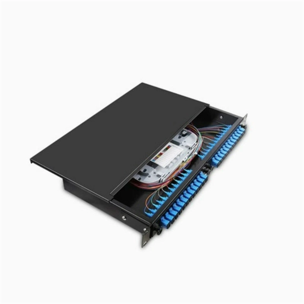
Optical module connected to lc
Most SFP fiber optic modules use LC connectors, while SC connectors are mainly found in legacy networks and MPO/MTP connectors are used for high-density cabling rather than directly on standard SFP modules. You may find LC connector has a strong family which includes but not limited to LC optical fiber connectors, LC fiber patch cables, LC fiber. This guide provides a fully updated and industry-ready overview of LC fiber optics, explaining the origin and design of LC connectors, their key features, and the complete ecosystem of LC-based products used in modern networking. Components and Structure There are two main components — the SFP transceiver and the LC connector in the SFP LC connector. The outer parts of the connector are precision plastic parts, including a push-pull plug-in clamping mechanism. Suitable for indoor applications in telecommunications and data network.
[PDF Version]
-

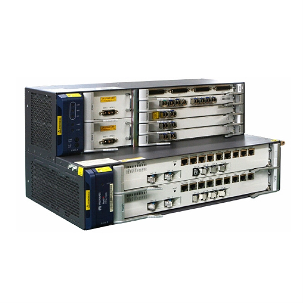
How to connect an optical port module to a router
Plug the SFP module into the router's SFP port for fibre optic connectivity. No additional settings need to be made. The assignment of any port on the built-in managed switch of the router can be changed according to the user's. This guide provides a clear, step-by-step explanation of how to install an SFP module correctly, based on real-world deployment practices. SFP Transceiver Module – Choose the appropriate module based on your network requirements (e., 1G, 10G. To plug in a fiber SFP (Small Form-factor Pluggable) module, follow these steps: 1. 1G/10G SFP+: Standard for Gigabit and 10 Gigabit Ethernet. To avoid static discharge damage, use an anti-static wrist strap. Installation Tips for. The SFP+ port is a high-speed optical-to-optical signal conversion port, mainly used for 10G Ethernet and Fiber Channel network applications.
-
Ciscoh3C optical module compatibility
Link to compatibility matrix tool: Click here. com The current compatibility matrix allows users, typically Cisco customers and sales, to determine what transceivers are supported in Cisco hardware devices such as switches/routers and line cards/modules. Cisco does not support third party optics. For the guideline on third party components, see Section 6 of Cisco's Non-Entitlement Policy. For ONS Family optics product and compatibility information, please click here For High-Density Fiber Patch Panel, Simplex, MPO and Breakout Cables Portfolio Data. Optical modules transmit signals over optical fibers. Optical transmission features low loss and is fit for long distance transmission. The information is displayed in a. The following table shows the available transceiver modules for interface modules, MPUs, subcards, and devices.
[PDF Version]
-
The chip used in the multimode optical module is
Their main chips include driver ICs, transimpedance amplifiers (TIA), laser chips (such as VCSEL), and control and digital diagnostic chips (MCU/EEPROM). These components collectively determine the performance, power consumption, and reliability of the optical module. Multimode optical transceivers are widely used in short-distance, high-speed interconnections in data centers. The transmitter converts the electrical signal into an optical signal, which is transmitted through optical fiber, and then the receiver converts the optical signal into an electrical signal. This. The optical module, known as Optical Transceiver in English, is a general term for various module categories, including optical receiver modules, optical transmitter modules, optical transceiver modules, and optical forwarding modules. An. Juniper Networks® has platforms ranging from the Juniper Networks CTP Series Circuit to Packet Platforms, BX Series Multi-Access Gateways, E Series Broadband Services Routers, M Series Multiservice Edge Routers, MX Series 3D Universal Edge Routers, to the T Series Core Routers.
[PDF Version]
-
What is the normal temperature for a base station optical module
The most common optical modules are C-TEMP, and their normal operating temperature ranges from 0 to +70℃. Selecting the appropriate temperature grade ensures that your network infrastructure operates optimally under varying environmental. Optical modules usually have different temperature grades, which are suitable for commercial, extended and industrial environments. Do you know the. The working temperature of the optical module has a greater impact on the use of optical modules, if the working temperature of the optical module is too high or too low, there will generally be a decline in optical power, low sensitivity, poor eye diagrams, in addition to accelerating the aging of. Why do optical modules need to be divided into so many temperature levels, and what are the differences between them? As one of the most important parameters of an optical module, the operating temperature can affect other parameters.
[PDF Version]
-
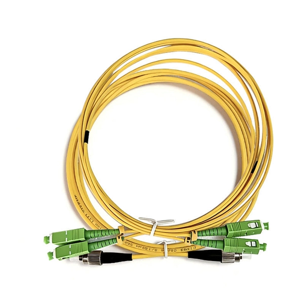
A single optical fiber uses a dual-core optical module
o In optical modules, "core" refers to the light-transmitting channel in the fiber. A 1-core module uses a single fiber core for data transmission, while a 2-core module uses two cores. They are easier to set up and give steady communication. A. Single fiber module also called BiDi transceiver or WDM module. BIDI module only has 1 port, wave filtering through the filter of module, and finished the transmitting of 1310nm optical signal. In today's communication field, single-core optical fibre and dual-core optical fibre are like remarkable stars, the powerful technology behind them and the disruptive impact on the communication industry deserve everyone's attention and discussion.
-
Which device should the optical module be plugged into
Optical modules can either plug into a front panel socket or an on-board socket. The optical module serves as a crucial component in optical fiber communication systems, operating at the physical layer, which is the lowest layer in the OSI model. Its primary function is to achieve optoelectronic conversion by converting electrical signals into optical signals and vice versa. Optical modules typically have an electrical interface on the side that connects to the inside of the system and an optical interface on the side that connects to the outside. The QSFP-DD, QSFP, and SFP transceiver modules are hot-swappable and connect the electrical circuitry of the system with an optical external network. The following figure shows the QSFP-DD transceiver, but the procedures outlined in this document apply to all pluggable transceivers. To aid in the task of choosing the right transceivers for your network, here are 6 key factors that should be reviewed with a transceiver/networ system specialist before making your final selections. These technical and operational.
[PDF Version]