-
What electrical components are commonly used in a display cabinet
An LED display is a complex system composed of several essential components, including LED modules, LED cabinets (panels), power supplies, control hardware, cables, fans, screws, braces, and connectors. These LEDs emit light in the three primary colors—red, green, and blue (RGB)—which combine to produce vibrant and dynamic color images. It typically includes a metal frame, power supply unit, signal distribution module, cooling system, and installation structure, providing a stable working environment for LED modules. 2 Core. LED screen components are essential parts of LED display devices. LED Screen Cabinet's External Frame The external frame supports all internal components. Power Cables Power cables are responsible for delivering stable, regulated power from the power supply units (PSUs). Comprehensive Guide to LED Display Connection for Power cables, signal cables, flat cables, LED screen modules, cabinets, video processor etc Would you like to know how to set up an LED display connection for cables, modules, controllers, or cabinets? When you buy an LED display, the process of.
[PDF Version]
-
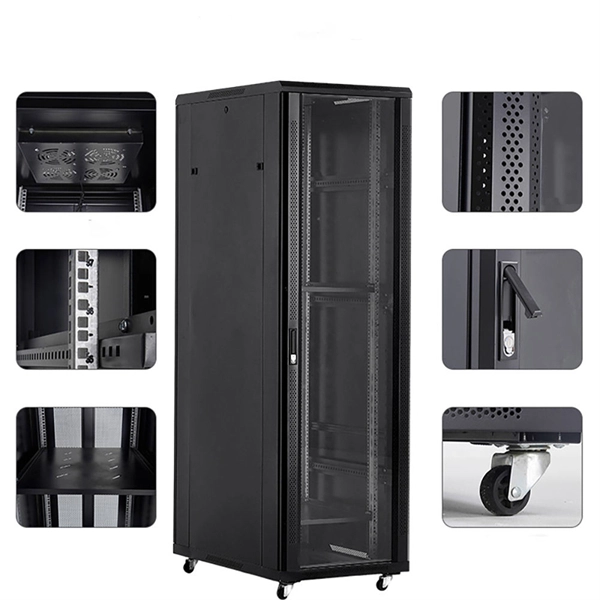
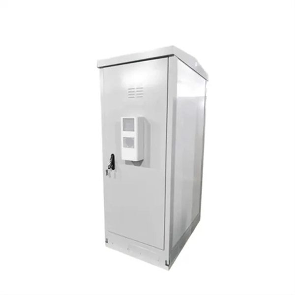
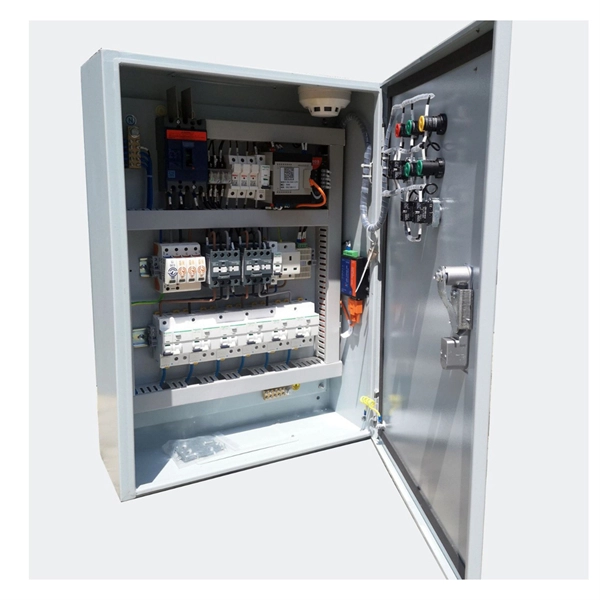
Wiring in distribution box floor cabinet
Wiring arrangement: Arrange the wires neatly in the box, fix them with zip ties, avoid wires from tangling or coming into contact with sharp edges, and reserve a certain amount of space for heat dissipation. A distribution box is the heart of any electrical system. It takes the incoming power and safely distributes it to different circuits throughout your building. more Learn how to wire a distribution box step by step! This video shows real on-site footage of. A well-chosen and properly installed distribution box can prevent electrical hazards, reduce downtime, and ensure your electrical system operates smoothly for years to come. This unique system increases the value of the infrastructure and meets the challenges posed by new construction and renovation in commercial offices, retail outlets an educational facilities. It is usually equipped with circuit breakers, fuses, terminal connectors, and other components. 50” from center of cutout to the.
[PDF Version]
-
Dominican Republic 5G Network Cabinet Costs
5G technology is at an early development and deployment stage in the Dominican Republic. The country's leading telecommunications companies are working to deploy 5G networks, but the technolo.
-
Design of Wavelength Division Multiplexing System
Normal WDM (sometimes called BWDM) uses the two normal wavelengths 1310 and 1550 nm on one fiber. Dense WDM (DWDM) uses the C-Band (1530 nm-1565 nm) transmission window but with denser. Wavelength division multiplexers are fundamental to the functioning and performance of integrated photonic circuits, with applications ranging from optical interconnects to sensing and quantum technologies. Current solutions are limited by trade-offs between channel spacing, crosstalk, insertion. In fiber-optic communications, wavelength-division multiplexing (WDM) is a technology which multiplexes a number of optical carrier signals onto a single optical fiber by using different wavelengths (i. The dissertation demonstrates 3 designs in silicon photonic CMOS co-design platform. 1515/joc-2025-0277 Mohammed, E. The "basie" transmission rate of SONET is 64 kbps for supporting voice communications. SONET multiplexes large numbers of 64-kbps channels onto higher-rate datastreams.
[PDF Version]
-
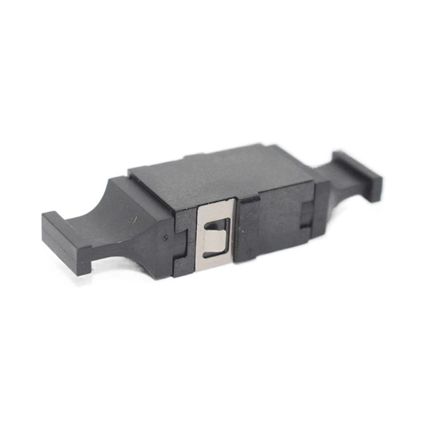
MEMS optical switch design
In figure 1.2 a row of protection switches is shown that is used in parallel optical connections (e.g. bus connections between computers). All channels have to be switched at the same time to reroute the signals from one computer to ano. In figure 1.2 a row of protection switches is shown that is used in parallel optical connections (e.g. bus connections between computers). All channels have to be switched at the same time to reroute the signals from one computer to another. Protection switching is required to avoid a permanent interrupt of a connection due to fiber break or due to. mirror / shutter surface micromachining Si-On-InsulatorElectromagnetic actuators are used in optical switches, as these actuators are known from precision machined solutions and the actuating part is a simple coil of many turns of wire. The ferromagnetic materials required in microsystems can easily be realized by sput-tering or electroplating of Permalloy. Additionally, the combination of permanent ma.
[PDF Version]
-
Fiber optic cable design reserve length
Standard/default length is 2 inches (reference), as produced by most label manufacturers. Marking details are based on MIL-STD-130 and will be legible and permanent. • Fiber optic cables are often custom cut to match required lengths for each cable run, or you can order a reel matching your total length and cut segments yourself. It's advisable to include a safety buffer when ordering, with an additional 10% being common practice, despite careful measurement of. Fiber optic network design refers to the specialized processes leading to a successful installation and operation of a fiber optic network. To calculate teh total number of fiber strands that will be required for the fiber optic cable installation, many people makes the mistake of underestimating the total. All lengths are calculated in a base unit, then converted. Reel count is ceil (Total ÷ ReelSize), and the rounded order length equals Reels × ReelSize. (FOA) was founded in 1995 to help develop the workforce to build the fiber optic networks to support a rapid expansion in communications and the Internet.
[PDF Version]
-

Emergency Circuit Design for Distribution Boxes
Size emergency and standby circuits with NEC 700/701, IEC 60364-5-56, UPS/generator transfer paths, and real voltage-drop examples. On a recent plan review, the riser looked clean: NEC 700 emergency lighting, a listed transfer switch, copper conductors, and breakers sized. Emergency and standby power systems are designed to provide an alternate source of power if the normal source of power, typically the electric utility service, should fail. Reliability of these types of systems is critical and good design practices are essential. Classification of Emergency and. Emergency system circuits supply power to critical life safety loads such as emergency lighting, fire alarm systems, fire pumps, smoke control systems, and essential communication and control circuits. Correct wiring design for emergency system circuits is essential to maintain power integrity. The National Electrical Code (NEC) Section 700. Under no. Another is to limit what qualifies as an “emergency load,” so the emergency system powers only what is needed to save human life (Fig.
[PDF Version]
-
Requirements for Relay Protection Design
The IEEE standard for protection relays refers to a collection of guidelines developed by the Institute of Electrical and Electronics Engineers. This document provides recommendations, background and philosophy on relay protection that is not available in M07. They are intended to quickly identify a fault and isolate it so the balance of the system continue to run under normal conditions. For professionals working in utilities, industries, or renewable energy systems, understanding these standards is not optional—it is essential. This handbook covers the code of practice in protection circuitry including standard lead and device numbers, mode of connections at terminal strips, colour codes in multicore cables, dos and donts in execution.
-

Principles and Product Design of Optical Fiber Communication
Optical Fiber Communication (OFC) revolutionizes modern telecommunications, enabling rapid data transfer across long distances with minimal signal loss. This comprehensive review explores OFC's historical evolution, core principles, components, and versatile applications. Kanade Department of Electronic-Science, P. College of ASC, Pravaranagar, India fPublished. The digital communication techniques discussed so far have led to the advancement in the study of both Optical and Satellite communications. Light acts as a carrier wave and can be modulated to carry information. Higher bandwidth (extremely high data transfer rate).