-
Circuit breaker distribution box installation price
Materials $450, labor $900, permits $0–$200, total $1,350–$1,550, per-breaker costs vary, overall project time 4–6 hours. Span reflects standard new breakers and enclosure. Mid-Range: 150–200A upgrade, some rerouting, outdoor panel, weatherproof box. Buyers typically pay for a circuit box replacement to upgrade to a higher amperage, improve safety, or meet code requirements. This article presents practical pricing in USD with clear low–average–high ranges and per-unit. Typical cost ranges for replacing a distribution box or service panel in the United States vary widely based on panel size, amperage, labor, and whether a full service upgrade is needed. ” At NUOMAK, we believe that your power. What is the average cost to replace a circuit breaker box? The average cost to replace a circuit breaker box in 2024 typically ranges from $1,500 to $3,500, with most homeowners spending around $2,000 to $2,500 for a standard replacement. This price can vary significantly based on factors like the.
[PDF Version]
-
Wiring of residual current circuit breaker in distribution box socket
In this video, I'll show you the complete wiring diagram of a home distribution board (DB). You'll learn how to connect the main circuit breaker (MCB), residual current device (RCD), and individual circuit breakers for lighting, sockets, and appliances. This guide provides a detailed, professional procedure for installing a Residual Current Circuit Breaker (RCCB)—a device essential for protecting people from the severe danger of electric shock. #dbbox #distribution #home #house. A distribution board or distribution box is where the main power supply is distributed to multiple loads. You will learn to build a safe, efficient, and professional electrical system today.
-
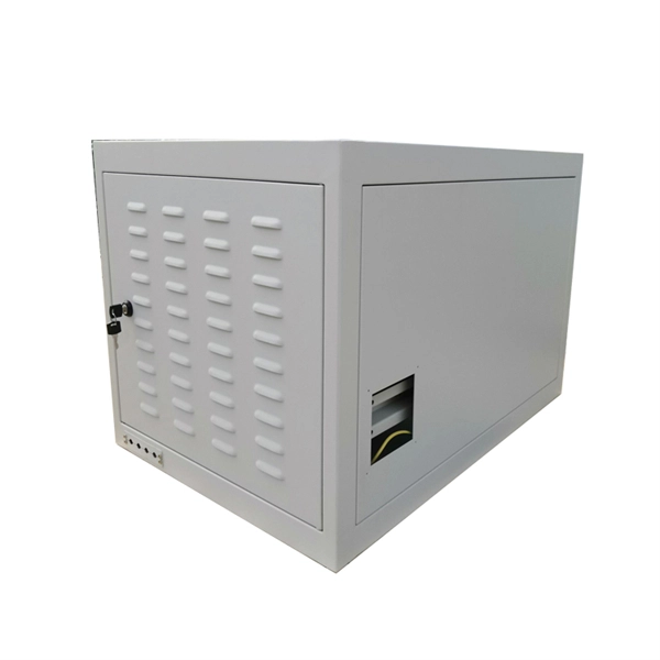
Distribution box circuit breaker obstructed
Check the electrical load and ensure that the sensors do not exceed the 10 Amp maximum. In this guide, we'll walk through these. Issue: Frequent tripping of circuit breakers is one of the most common issues in distribution boards. It can occur due to overloaded circuits, short circuits, or ground faults. Using a light switch as a simple example, check each of the three wires.
-
Distribution box circuit breaker malfunction
It can occur due to overloaded circuits, short circuits, or ground faults. Solution: Identify the Cause: Check if the breaker is tripping due to overloading. This often happens when too many devices are plugged into one circuit. Reducing the load on the circuit or redistributing. Distribution boxes are the unsung heroes of our electrical systems, quietly managing power until something goes wrong. Overheating can damage the entire distribution box or even. This guide will help you identify and solve common circuit breaker problems effectively, so you can prevent disruptions and avoid expensive repairs.
-
The circuit breaker in the building s electrical distribution box tripped
Electric recommends these steps to restore power safely when your circuit breaker trips. Reset the breaker by switching it fully off, then back on. Circuit breakers are switches that disconnect electrical circuits by interrupting the current running through them. “Circuit breakers. To effectively troubleshoot a tripping breaker, you should begin by identifying potential causes, such as overloaded circuits, short circuits, or faulty wiring. Add Bob Vila Adding us as a Preferred Source in Google by using this link indicates that you would like to see more of our content in Google News results.
-
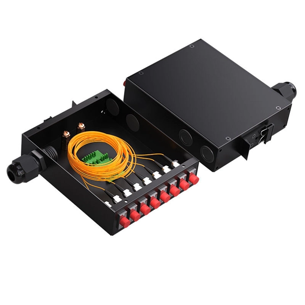
Correct circuit breaker configuration in the distribution box
This guide shows you how to organize circuit breaker wiring properly. You will learn to build a safe, efficient, and professional electrical system today. Circuit breaker wiring configurations involve organizing main switches, busbars, and branch breakers within a distribution box. Electrical distribution diagrams can help you see how things are connected. It serves as a central hub for distributing electricity throughout a building, ensuring that power is delivered safely and efficiently to all the required locations.
-
Industrial Switch Circuit Breaker Rail
Also known as supplemental protectors, these circuit breakers mount directly to DIN rail downstream from a branch circuit breaker to protect a single piece of equipment. They are rated UL1077 for protectio.
-
Configuration of circuit breakers in large household electrical distribution boxes
Reducing Number of Poles: Use 1P or 1P+N circuit breakers where appropriate, reserving 2P breakers for the main switch and high-power circuits. Why do you need GFCI or AFCI breakers? Choosing the right size and setup for your distribution box keeps your electrical system safe and working well. You lower the chance of circuits getting too hot or overloaded when you pick the right box for your needs. Circuit breaker wiring configurations involve organizing main switches, busbars. The circuit breaker switch in the household distribution box depends on the area of the owner's house in the community. However, no matter how large. PRO TIP: Wiring a panel is complicated, so many electricians divide the task into steps—cutting wires to length, stripping wire ends, bending wires toward a bus, tightening bus screws—and perform each step on all wires before going on to the next step. Fortunately, there's more room in the main electrical panel than meets the eye if you utilize tandem circuit breakers. Double-pole breakers are shown in locations 1 and 3, and 13 and 15. Instead of providing 120 VAC, these “doubles” provide 240 VAC to the load. A tie bar physically connects the two.
[PDF Version]
-
Requirements for Optical Module Circuit Boards
Since they are used to interconnect electronic devices, optical module PCBs are designed to meet several requirements, such as supporting high-speed data transmission, dissipating heat, and enabling hot-swapping. Optical module PCB design demands exceptional accuracy to ensure stable and. This guide serves as an in-depth resource for engineers, designers, and project managers involved in the development of optical module PCBs. 1 mm in thickness, with most designs comprising ≤12 layers. These materials lower energy loss and help high-frequency work better.
-

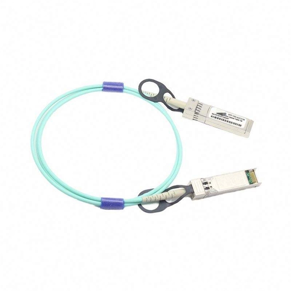
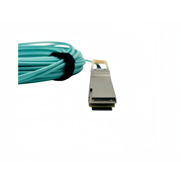
Which type of pigtail fiber suffers the least loss
One of the key advantages of LC pigtails is their low insertion loss, which ensures minimal signal degradation during transmission. Executive Summary: A fiber optic pigtail is one of the most commonly specified yet least understood components in structured cabling. Get the wrong connector type, the wrong polish, or skip proper fusion splicing technique—and you're looking at elevated signal loss, increased back reflection, and a. A fiber optic pigtail is a short length of optical fiber —typically 0. 5m to 2m—that has a factory-terminated connector on one end and bare fiber on the other end. For non-permanent connections, one can also use fiber connectors (see below). Figure 1:. They were all the wrong polish type. The network failed during testing. I've seen every kind of setup — from data centers to.
-
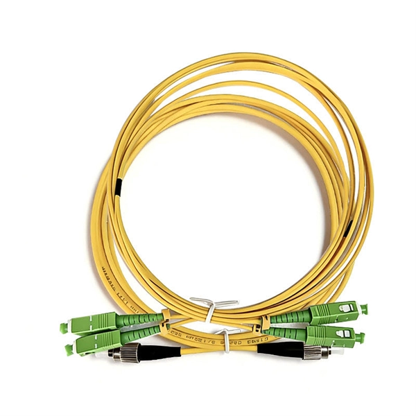
Pigtails are a type of optical fiber
A fiber optic pigtail is a short optical fiber cable that has a connector on one end and an exposed (unterminated) fiber on the other. The connector end plugs into devices like transceivers or patch panels, while the bare end is typically fusion spliced to a fiber optic cable. They are the bridge between fiber optic cables in the field and the equipment or patch panels that manage them. By combining factory-installed connectors with spliced bare fiber, pigtails ensure that network installers can create. Executive Summary: A fiber optic pigtail is one of the most commonly specified yet least understood components in structured cabling. Get the wrong connector type, the wrong polish, or skip proper fusion splicing technique—and you're looking at elevated signal loss, increased back reflection, and a. A fiber pigtail is typically a fiber optic cable with one end factory pre-terminated fiber connector and the other exposed fiber.
[PDF Version]