-
Technical Requirements for High Voltage Busbar Manufacturing
The technical requirements for battery pack copper busbars cover five aspects: materials, electrical performance, mechanical properties, environmental adaptability, and safety. This section outlines general requirements; specific details should be tailored to application scenarios. This document is applicable to the fabrication and assembly of busbars for. Busbar design within Medium Voltage (MV) switchgear is a critical aspect, fundamentally ensuring the safe, reliable, and efficient operation of power systems. These busbars are not merely simple current conductors; they serve as the strategic backbone, interconnecting various components within the. This article is for manufacturing, testing of non-segregated Bus Bars and Bus Ducts rated 600 V to 35 kV as per international standard ANSI C37. Plan for continuous current + surge; hotspots often occur at studs and.
[PDF Version]
-
East Africa High Voltage Common Enclosed Busbar Trunking
Busbars are available from 63A up to 6000A, are compact, can be installed edgewise, flat or vertically and in any restricted space. The busbars can be supplied with aluminium or copper conductors and are insulated with suitably pre-shaped, self-extinguishing material complying. List Price R 205. VAT List Price R. Busbar Trunking Systems is used for electricity distribution and is an alternative for cumbersome conventional cable systems • DBTS Africa busbar systems are designed and manufactured utilizing state-of-the-art technologies and equipment. With one of the most comprehensive ranges, we offer solutions from 25A lighting Busbar through to 6,300A LV and 24kV MV Busbar systems, including rising mains. (formerly Zhenjiang Dingsheng Electric Appliance Co.
-
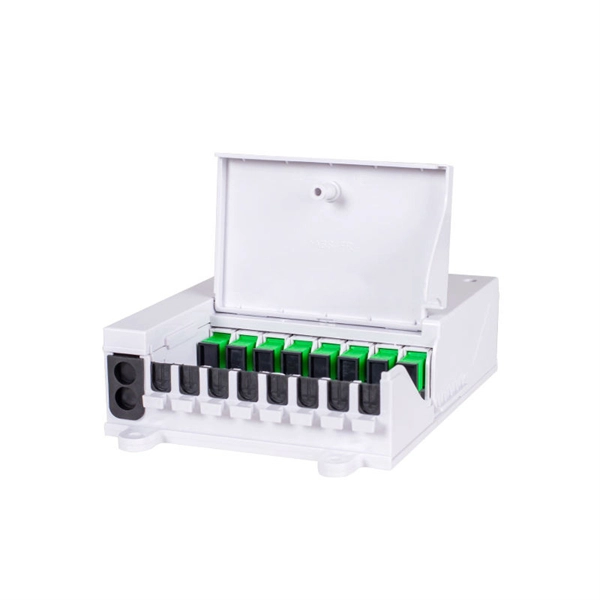
Fiber optic cable splicing techniques using heat shrink tubing
Carefully release each cable from splicer clamps. Slide shrink sleeve over exposed fiber and place in splicer's heating compartment; sleeve should cover each side roughly 3cm from joint. Consult the cable spec fication sheet for the cable you are installing. 1dB for fusion) and degrade over time in outdoor environments. A professional splice kit includes: Every splice starts with proper preparation: clean the work area, protect against wind, and. Single holed (preshrunk) ends eliminates improper fiber threading. Extended liner length prevents contact between the fiber and their backbone. Clear sleeve design permits easy centering. There are 7 procedures to perform in the splicing process; roughly in the following order: Procedures 2 and 3 will be performed twice; once for each of the two cables. Preparing to Use Heat Shrink Wrap: - Slide heat shrink wrap through one end of the fiber optic. A fiber optic heat shrink tube is used for reinforcing the splice connection.
[PDF Version]
-
The 10kV busbar has been changed from maintenance to operation
There are many standards on the subject pertaining to different voltage levels of switchgear, which normally defines four separate aspects of maintenance, with each new stage based on the preceding one, 1. Inspection, 2. Servicing, 3. Examination and 4. Overhaul. These are dealt with in detail below:Maintenance covers a wide range of activities, all of which are required to keep the switchgear in ready condition at all times to enable it perform its functions satisfactorily. The parts subjected to normal wear and agingneed to be serviced for ensuring full reliability of the operations. These parts may be mechanical components or electrical com. Safety features need to be planned before switchgear units are ordered. The requirement of locking off parts of the system (for carrying out maintenance work on the associated plant) should be finalised. Proper interlocking arrangements should be provided for this purpose. All metal-enclosed switchgears are designed so that all live conductors are.
[PDF Version]
-
10kV Busbar Voltage Testing Standard
IEC 61439 is a standard developed by the International Electrotechnical Commission (IEC) that covers design verification for low-voltage electrical products and assemblies. The IEC 61439. 7 cycles of 24 h each to salt mist test according to IEC 60068-2-11; (Test Ka: Salt mist), at a temperature of (35 ± 2) °C. The test shall be carried out according to IEC 60068-2-2 Test Bb, at a temperature of 70 °C, with natural air circulation, for a duration of 168 h (7 days) and with a recovery. ULTRUS™ helps companies work smarter and win more with powerful software to manage regulatory, supply chain and sustainability challenges. Consistent performance benchmarking testing capabilities for professional PC users. Award-winning software and advisory services for ESG management and. The purpose of this method is to verify the functionalities of a Metal Enclosed Busb ar. How do you check and maintain busbars? What are the faults of busbar? What is bus bar in DB? For complete safety instructions and precautions, always refer to the test equipment instruction manual.
[PDF Version]
-
Maximum allowable voltage drop value of 10kV busbar
The formula used is IMAX = (I * 100) / (100 + VD), where I is the busbar current rating and VD is the allowable voltage drop. Typical values for LV installations are given below in Figure G27. 1) These voltage-drop limits refer to normal. Instant voltage drop limits calculator: NEC and IEC compliant, auto-applies 3%/5% rules for lighting, feeders. Enter nominal voltage and optional measured drop; get pass/fail, max allowable volts, length helper instantly. Design by percent limits: compute max length, minimum size or actual drop. Voltage drop is the reduction in voltage along a bus bar due to its resistance. This standard defines the design verification, test requirements, and thermal performance of the assemblies.