-

How to connect the 10 Gigabit Ethernet cable to the fiber-to-electrical port module
A special 10G Copper RJ-45 Transceiver (10G-SFP-T) is required to connect the SFP+ port to RJ45. It allows connecting a server/storage side Cat6/7 cable to an SFP+ port transceiver. An SFP module (or optical transceiver) converts electrical signals from network devices (switches, routers) into optical signals for fiber transmission and vice versa. 1G/10G SFP+: Standard for Gigabit and 10 Gigabit Ethernet. These transceiver modules are hot-swappable input/output (I/O) devices that plug into 100BASE, 1000BASE and 10GBASE ports (for SFP+), which connect the module port with the fiber-optic or copper network. 4ft (30m) * using Cat6a/Cat7 or above cable for 10G connection in various applications. In this video, we'll guide you through building a high-speed 10G LAN by connecting two fiber switches. Finally, check the transmit (TX) and receive (RX) paths to ensure that signals are aligned.
[PDF Version]
-
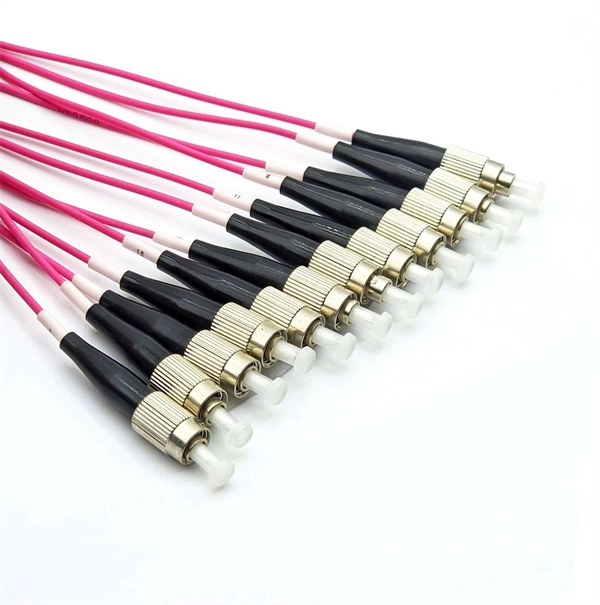
10 Gigabit Ethernet card optical module not connected to fiber optic cable
Troubleshooting SFP+ link issues in 10 GbE networks requires attention to module type, match of speed and wavelength, clean fiber connections, correct configuration, thermal management, and equipment compatibility. You can quickly resolve SFP+ Module connectivity issues by following a systematic optical transceivers troubleshooting process. Check for common connection problems, such as link failures or modules not recognized. Check compatibility between the optical module and switch Most switch brands have specific compatibility requirements. During network upgrades, many enterprise users encounter a common issue: after replacing 10G broadband lines or inserting 10G SFP+ optical modules, the switch still fails to operate at full 10G bandwidth or even fails to recognize the modules. We've listed the five most common ones. First of all, let's briefly recap what SFP and SFP+ stand for. SFPs – short for 'small form-factor pluggable' – are compact, hot-pluggable devices.
[PDF Version]
-
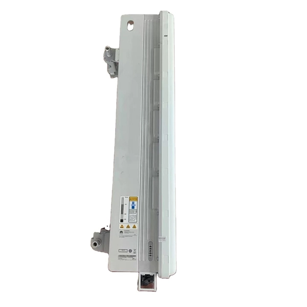
Switches are all 10 Gigabit optical
To implement different 10GbE physical layer standards, many interfaces consist of a standard socket into which different physical (PHY) layer modules may be plugged. PHY modules are not specified in an official standards body but by (MSAs) that can be negotiated more quickly. Relevant MSAs for 10GbE include (and related X2 and XPAK), and. When choosing a PHY.
-
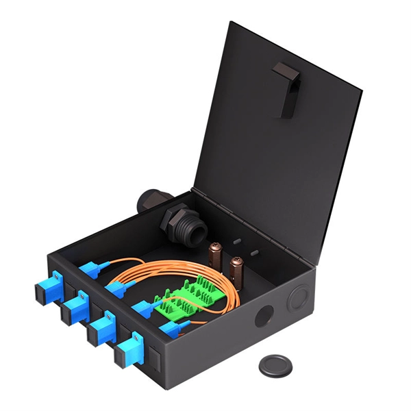
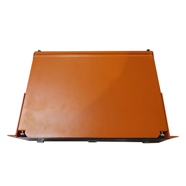
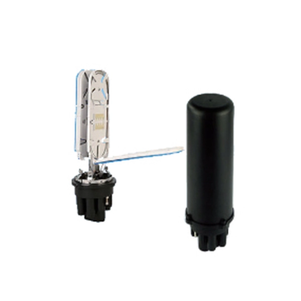
The function of a 10 Gigabit optical splitter
By dividing a single optical signal from a central Optical Line Terminal (OLT) into multiple outputs for Optical Network Terminals (ONTs) at users' homes, splitters eliminate the need for dedicated fibers to each residence—slashing infrastructure costs while scaling network reach. An Optical Splitter, also known as a beam splitter, is a passive optical device that divides a single input optical signal into two or more output signals. Conversely, it can also combine multiple signals into one. Optical splitter. Where splitters are placed in the network can make significant impacts on fiber counts, network cost and deployment time and operational steps, such as customer onboarding and maintenance. One important note is that splitting architectures should be seen as tools that can be mixed and matched to. The trick is how that single signal gets divided. That's where splitters come in.
[PDF Version]
-

Function of Busbars in High Voltage Switchgear
A busbar is a metal bar, usually made of copper or aluminum, that carries electricity inside switchgear. It connects the incoming power to circuit breakers and outgoing circuits, helping power flow smoothly and evenly. Good busbar design helps prevent overheating and electrical. Busbar design in switchgear ensures safe, reliable power distribution by balancing current capacity, thermal performance, mechanical strength, insulation, and standards compliance. Electrical busbars are solid conductors used to carry and distribute high current in switchgear, panels, substations, and power systems. This guide explains how busbars work, common types, key design factors, and how to choose the right busbar for your application. Instead of running numerous.
-
Voltage of the switch in the home s electrical distribution box
The following tutorial shows how to wire 120V single phase breaker box installation in home. 120V single phase circuits are generally used in home wiring for lighting circuits and outlet receptacles. To do.
-
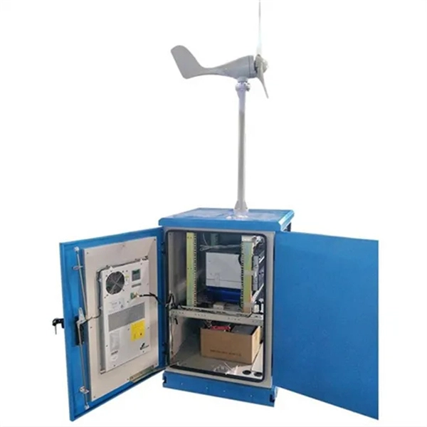
Insufficient voltage at remote end of centralized power supply
The most common solution to this problem is to enable the supply to measure the output voltage at the load instead of at the output terminals. This methodology is called “remote sense”. How does remote sense work?An error in the DUT voltage measurement is due to the output current and the resistance of the leads used to connect the power supply or SMU to the load. This error can be calculated using the following equation: Local Sense Error (Volts) = Iout (Rlead1 + Rlead2) When the device is operating in. Remote feedback to differential amplifier compensates for Senior Applications Engineer parasitic-resistance voltage drop processors. As systems push tighter tolerances and higher currents, these drops become harder to ignore. Remote sense provides a straightforward way to correct them by letting. This simple, un-avoidable truth dictates that a power source's remote load voltage will be less than the source's output voltage. By default, the load operates in local sense, where feedback is internally connected to the load's input.
[PDF Version]
-
There is voltage between the neutral wire and the outer casing of the distribution box
At panelboards, the voltage difference between the neutral conductor and the equipment grounding conductor (panelboard case) will be equal to the voltage drop of the feeder neutral conductor, which is 3 volts. When a neutral wire carries voltage, it poses risks such as electric shock, equipment damage, and other hazards that can disrupt daily life and production. Understanding the causes behind this phenomenon is crucial for identifying and addressing the issue effectively.
-
Maximum allowable voltage drop value of 10kV busbar
The formula used is IMAX = (I * 100) / (100 + VD), where I is the busbar current rating and VD is the allowable voltage drop. Typical values for LV installations are given below in Figure G27. 1) These voltage-drop limits refer to normal. Instant voltage drop limits calculator: NEC and IEC compliant, auto-applies 3%/5% rules for lighting, feeders. Enter nominal voltage and optional measured drop; get pass/fail, max allowable volts, length helper instantly. Design by percent limits: compute max length, minimum size or actual drop. Voltage drop is the reduction in voltage along a bus bar due to its resistance. This standard defines the design verification, test requirements, and thermal performance of the assemblies.
-
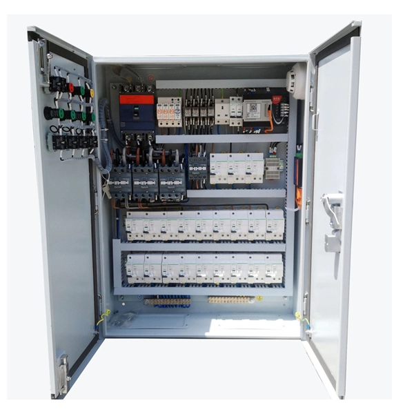
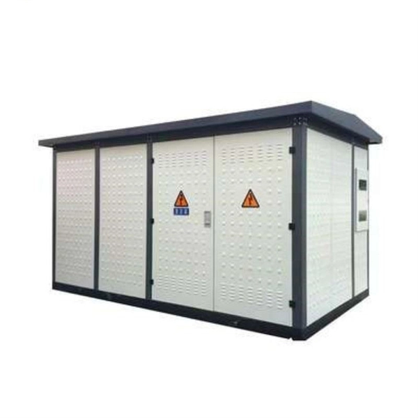
Voltage Classification of Distribution Boxes
Distribution boxes can be broadly categorized by their voltage level, application environment, and primary function. The two most fundamental distinctions are between Low-Voltage Distribution Boards and Medium-Voltage Distribution Enclosures, often referred to as Ring Main Units. In this guide, we'll break down the 12 main types of distribution boxes in a way that's easy to understand. We'll chat about what each one does, where it shines, and then dive into how to choose the perfect box for your needs. Plus, we'll sprinkle in some practical tips to make sure you're not. The purpose of this document is to provide general information on the definitions of NEMA Enclosure Types to architects, engineers, installers, inspectors and other interested parties. Many companies are adopting zero energized work policies. Power. Box substations are integral components of power distribution systems, playing a crucial role in transforming and distributing electrical energy.
[PDF Version]