-
Local Area Network Optical Module Solution
One such solution is Passive Optical LAN (POL), an innovative alternative to traditional Ethernet-based Local Area Networks (LANs). By leveraging fiber-optic technology, POL provides numerous benefits such as improved performance, cost savings, and enhanced network scalability. This article covers every. ltiple tiers of electronics are used to connect users. Ethernet switches in the equipment room are connected via optical fibr to aggregation switches in telecommunication closets. I with passive optical splitters and single-mode fibres. Cisco's Routed PON Solution is a transformational approach that condenses the OLT chassis into a pluggable form factor.
-
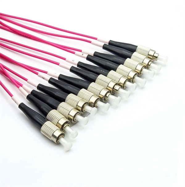
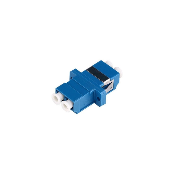
Optical module connected to lc
Most SFP fiber optic modules use LC connectors, while SC connectors are mainly found in legacy networks and MPO/MTP connectors are used for high-density cabling rather than directly on standard SFP modules. You may find LC connector has a strong family which includes but not limited to LC optical fiber connectors, LC fiber patch cables, LC fiber. This guide provides a fully updated and industry-ready overview of LC fiber optics, explaining the origin and design of LC connectors, their key features, and the complete ecosystem of LC-based products used in modern networking. Components and Structure There are two main components — the SFP transceiver and the LC connector in the SFP LC connector. The outer parts of the connector are precision plastic parts, including a push-pull plug-in clamping mechanism. Suitable for indoor applications in telecommunications and data network.
[PDF Version]
-
Is the R-port on the optical module for receiving or transmitting light
ROSA is the component inside the receiver side of the SFP port. The ROSA is responsible for receiving the optical signal transmitted by the TOSA of the opposite end's transceiver and converting it back to an electrical signal so that the communication equipment can understand it. Optical modules typically have an electrical interface on the side that connects to the inside of the system and an optical interface on the side that connects to the outside. The integrated optical transceiver module is the core device of optical communication, which completes the optical-electrical/electrical-optical conversion of optical signals. We'll cover everything from physical form factors to spectral characteristics, modulation formats. Ensures a proper connection between the optical module and the optical port of the device. It exists only on an SFP optical module.
[PDF Version]
-
What does eq mean in the optical module
They refer to the equalization settings applied to the received signal (RX) and transmitted signal (TX) in optical transceivers. The idea is simple: instead of a DSP (digital signal processor) inside the module – replacing it with transimpedance amplifier (TIA) and a driver chip with high linearity and EQ capability – LPO shifts signal processing into. Outputs a True value when its inputs are equal in value. The output is True only if the input values are equal in value. Function Block Diagram - EQ: An EQ function has 2 inputs (in this case, 2 constant. The optical module serves as a crucial component in optical fiber communication systems, operating at the physical layer, which is the lowest layer in the OSI model. What do they mean and how can we understand them? Let's break down what they mean so you can easily understand them. more In fiber optic communication, optical modules are key. This manual contains notices you have to observe in order to ensure your personal safety, as well as to prevent damage to property.
[PDF Version]
-
APM Optical Flow Module Debugging
Cut and resolder the MISOLVL jumper on the back of the board to switch the MISO pin to work on 3. If the sensor is mounted to a stabilized gimbal or mount, set FLOW_OPTIONS bit 1 to “1”. To know more about our new products, please visit www. com, we will serve you wh eed for GPS. This is critical to ensure the optical flow sensor does not interfere with APM is a open source flight control system, it is a multifunction system that can support quadrocopter, as well as aircrafts of fixed -wing, three-axis, 6-axis,8 –axis etc. APM flight control is a rather mature technique with formidable capabilities: it supports GPS designated cruise and automatic. Instead please use the PX4Flow sensor. The PX4FLOW is not yet supported in Plane or Rover. These are camera modules that use ground texture and visible features to determine aircraft ground velocity.
[PDF Version]
-
Which to choose a single-port optical module or a dual-port optical module
Single fiber transceivers use one fiber to send and receive data. They are cheaper and good for networks with few fibers. It uses WDM technology to realize the bidirectional transmission of optical signals on one optical fiber. 🔍 Basic Differences ⚠️. Small Form-Factor Pluggable (SFP) modules are widely used in data centers, enterprise networks, telecom infrastructure, and FTTH (Fiber to the Home) deployments. In fiber optics, the data is sent in the form of light pulses or signals at high speeds and over long distances.
-
How to enable the optical module after plugging it into the optical port
Align the SFP module with the optical port and insert it horizontally, pressing firmly until the bottom of the module engages with the locking spring of the optical interface. Figure 1 SFP Optical Module Installation. The Cisco Small Business Series Switches allow you to plug in a Small Form-factor Pluggable (SFP) transceiver in their optical modules to connect fiber optic cables. Once the transceiver and fiber optic cable are plugged in properly in the switch optical module, you should be able to view the. This section describes how to install optical transceivers on the SFP or SFP+ ports and connect them to the ports of the peer device using optical fibers according to the network plan. The USG supports both 1 Gbit/s, 10 Gbit/s, and 40 Gbit/s optical modules. The LED will only light up when all connections are properly established and functioning correctly. The installation process can be taken by the following instructions.
[PDF Version]
-

Correct Method for Testing Optical Power Meter Readings
Use an optical power meter for this task. You use it to measure the strength of light signals in fiber optic cables. The basic process is straightforward: turn the meter on, set it to the correct wavelength, clean your connectors, plug in, and read the. FOA "Quickstart Guides" are short, simple guides to basic fiber optic tests.
-
What is an optical module and its application scenarios
An optical module is a small device that moves data using light. It changes electrical signals into light signals and back again. This helps data travel faster and farther than with copper cables. Optical modules are very important for fast internet, cloud computing, and other. When it comes to optical modules, I'm sure everyone is quite familiar with them. Optical modules typically have an electrical interface on the side that connects to the inside of the system and an optical interface on the side that connects to the outside. As an essential component of optical fiber communication, optical modules are optoelectronic devices that facilitate the conversion between optical and electrical signals during the transmission process. An. Aerech Networks will use this article to introduce you to the application scenarios of optical modules.
[PDF Version]
-
Increase the light output power of the optical module
An optical amplifier is a device which receives some input signal light and generates an output signal with higher optical power. Typically, inputs and outputs are laser beams (very rarely other types of light beams), either propagating as Gaussian beams in free space or in a fiber. At the receiver end, the optical signals are reconverted into electrical. In this guide, we will explain what optical signal strength is, how to check it on Cisco IOS using the command line, and how to troubleshoot common light level issues. Assume the. This application note gives a short introduction to optical modules and the need of an optimized power tree in them and then concentrates on the use cases and benefits of four-switch and inverting buck-boost converters inside optical modules.
-
When will Xiaomi s optical module be released
Xiaomi has recently made waves in the tech world by launching its groundbreaking modular optical system at MWC 2025. This innovative accessory is designed specifically for the Xiaomi 15, featuring a detachable 35mm lens that transforms mobile photography. Let's get into the details! The module is centered around a 100MP micro four-thirds sensor, paired with a 35mm f/1. The Chinese firm has yet to reveal whether it plans to bring the product to. Tech Advisor reports Xiaomi's modular camera lens concept is entering mass production after being showcased at MWC 2025.