-
-
-

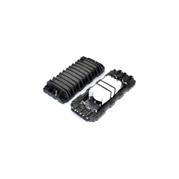
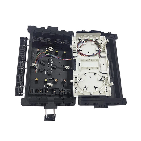
What is the mechanical splicing method for optical cables
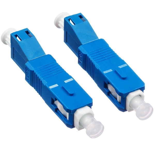
Mechanical splicing is the process of precisely aligning two fiber optics together using an alignment device and index matching gel that has a similar refractive index and covers the possible air gaps, helping light travel from one fiber to another with minimal loss and little back. Mechanical splicing is the process of precisely aligning two fiber optics together using an alignment device and index matching gel that has a similar refractive index and covers the possible air gaps, helping light travel from one fiber to another with minimal loss and little back. A mechanical splice is a junction of two or more optical fibers that are aligned and held in place by a self-contained assembly (usually the size of a large carpenter's nail). The fibers are not permanently joined, just precisely held together so that light can pass from one to another. This. Mechanical splices are used to create permanent joints between two fibers by holding the fibers in an alignment fixture and reducing loss and reflectance with a transparent gel or optical adhesive between the fibers that matches the optical properties of the glass. Before you move forward with your fiber optic installation, it is vital for you to have a fairly good understanding of both methods. This would help you determine which technique. There are two main methods of splicing: mechanical splicing and fusion splicing. -
-
The Development History of Fiber Optic Acoustic Sensors
Fiber-optic interferometric acoustic sensors were first proposed for US Navy applications 36 years ago. This paper will review the origin, development and deployment of these sensors. Future applications will also be discussed. This content is available for download via your institution's subscription. To access this item, please sign. Fiber‐optic sensor technology has experienced tremendous growth since its early beginnings in the 1970s with early laboratory demonstrations of fiber‐optic gyros and acoustic sensors and the introduction of the first commercial intensity and spectrally based sensors. These early efforts were. The Design Of Fiber Optic Sensors For Measuring Hydrodynamic. Navy's effort to develop sensors that used optical fiber to detect targets at sea offers a window into how a technology goes from basic research to production. -
Minimum Ampere Capacity for a Secondary Distribution Box
This revision released concurrently with Standards and Equipment Advisory Information Bulletin 2024-014 Revised ES54 S1-01 Secondary Single-Phase Services 200 A Single and 400 A Multiple Self-Contained Meter Installation. This document shows the methods and requirements for installing PG&E-owned, underground service cables in customer-owned, residential, terminating facilities. REFERENCES This. talled today include 100 Amps (A) and 200A. The meter socket, which provides connection t considerations impacting electrical upgrade requirements and related costs. Electrical distribution diagrams can help you see how things are connected. Diagrams act like a map for your electrical system. NEC Article 408 covers switchboards, switchgear, and Panelboards installation and applications. -
-
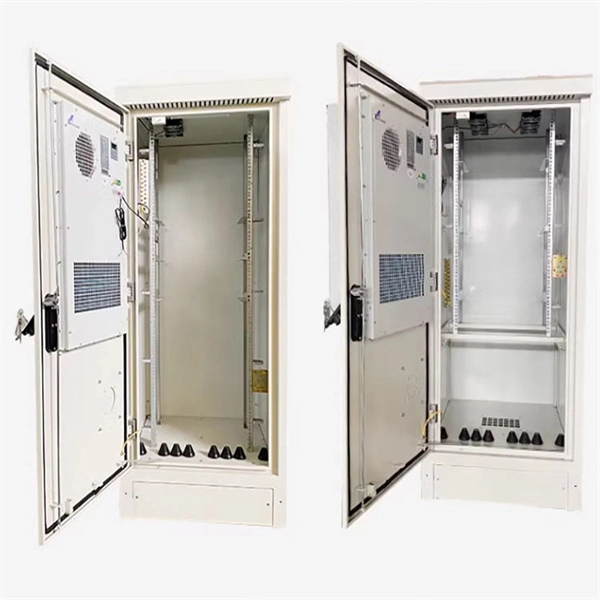
Standard Level 1 Distribution Box at Construction Site
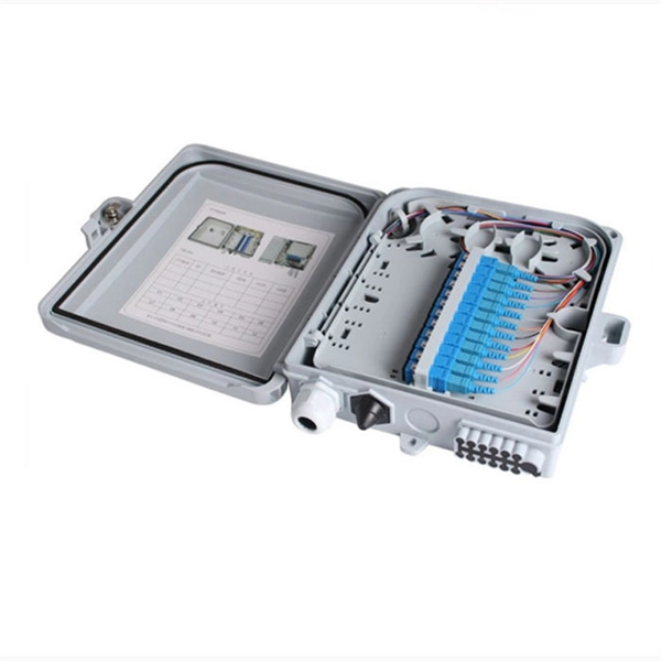
Check for proper IP/NEMA ratings and material quality. Ensure safe placement: install in dry, accessible areas with good ventilation and at appropriate height (typically ~1. Practice good wiring: secure grounding, neat cable management, proper insulation, and correct wire gauge and. In this documentation package, Duke provides comprehensive construction specifications in effect on July 1, 2021, to the Interconnection Customer. The outgoing line from the low-voltage end of the transformer is 0. 4kV to. JECT TO UPDATE AND MODIFICATION AT ANY TIME. TO EVERY CIRCUMSTANCE OR ELECTRICAL SYSTEM. SRP ENCOURAGES EACH USER TO CONSULT WITH ITS OWN TECHNICAL ADVISOR CONCERNING THE APPLICABILITY OF THESE TANDARDS TO. Appendix A added references to IEEE Guides mitigating bird and wildlife-related power interruptions. The Unified Facilities Criteria (UFC) system is prescribed by MIL-STD 3007 and provides planning, design, construction, sustainment, restoration, and modernization criteria, and applies to the. This standard describes the design of individual electrical power circuits for illumination, signal, and ITS equipment, powered from WSDOT electrical service cabinets, and the associated features required in the service cabinet to support these circuits. This standard only addresses fixed (or. -
-
Silicon Photonics Chip Technology Updates
Silicon photonics has developed into a mainstream technology driven by advances in optical communications. The current generation has led to a proliferation of integrated photonic devices from thousands to millions-mainly in the form of c. Silicon photonics has developed into a mainstream technology driven by advances in optical communications. The current generation has led to a proliferation of integrated photonic devices from thousands to millions-mainly in the form of communication transceivers for data centers. Products in many exciting applications, such as sensing and computin. Figure 1 maps the evolution of silicon photonics1,2. Silicon-based photonic integrated circuits (PICs) were introduced in 19853 and low-loss waveguides in a thick silicon on insulator (SOI) process demonstrated in 1991–924,5. Various optical devices were next demonstrated6, and soon, silicon photonics was in the small-scale integration (SSI) era—with 1-to-10 components on a PIC. They included demonstrations of high-speed pn junction modulators7,8,9 and photodetectors (PDs)10,11,12,13, as well as heterogeneous integration of a III-V laser to a silicon PIC14. The next era ushered in the commercial success of silicon photonics. With 10-to-500 components on a PIC, this medium-scale integration (MSI) era saw successful demonstration and adoption of Mach-Zehnder modulator (MZM) in intensity-mo. Through the generations of CMOS process development, many materials were added to silicon to reduce the Power, improve the Performance, and shrink the Area—often called the PPA metrics. The additions include Al and Cu for metal traces, Ge for inducing strain and enabling heterojunction BJTs, and silicon nitride (SiN) for passivation and diffusion barriers. The CMOS R&D budgets and commercial markets are orders of magnitude larger than for silicon photonics, so it is natural for silicon photonics foundries to learn from and adopt the innovations from CMOS processes. Hence, we have seen a similar trend in silicon photonics process development. Besides p/n dopants for high-speed modulation, two materials that are now natively supported by several foundries are (1) Ge high-speed photodet. Photonics & electronics interplaySilicon PICs almost always exist in conjunction with electronic ICs (EICs). When we look at systems based on photonic chips, the landscape today is almost 100% dominated by data communication, and we expect this to continue for the near future. In this context, EICs serve two purposes (Fig. 2): (1) Enable E/O and O/E conversions of the end-to-end data. (2) Bias, control and compensate for temperature and fabrication variations. Thus, photonics serve electronics by providing the data links, and electronics serve photonics by providing control and readout and digital signal processing (DSP). A major difference between photonics and electronics is that photons don't interact and thus are excell. In this section, we describe the top technical impediments to the success of various silicon photonics applications (Table 5), connecting them to some of the challenges and opportunities discussed in previous sections. We limit the impediments to PIC/EIC technology only, excluding economic, regulatory, market, and other factors such as chemistry, biomarkers, quantum advantage, etc. We also do not delve into the benefits of silicon photonics for these applications since most of the previous works describe them in detail.Full size tableFor IMDD transceivers (XVRs) to further improve their energy efficiency (pJ/b) and scale to higher data rates, the modulator. -
What to do if the optical power meter signal is inaccurate
The magnitude of this error is a function of both wavelength and connector type, and, as a result, the power meter should be calibrated with the same fiber and connector with which it is to be used. Below are general answers on how to operate, maintain, and calibrate an optical fiber ranger from the list of GAO Tek's optical power meters. Power On: Ensure the device is charged or properly connected to a power source. Turn on the optical power meter (OPM) using the power button. Optical power meters are essential tools for anyone working with fiber optic networks, allowing you to measure the strength of an optical signal with precision and accuracy. Here are five tips to. According to IEEE 802. OSA (Optical Spectrum Analyzer) - For Coherent Systems Ideal for DWDM/CWDM modules. Accurately testing an optical Transceiver means proving two things: that the module is emitting the right power at the right wavelength, and that the link it's attached to delivers that signal without unexpected loss or reflections. -