-
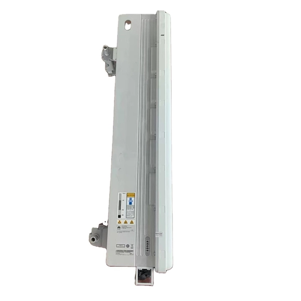
10 Gigabit Ethernet card optical module not connected to fiber optic cable
Troubleshooting SFP+ link issues in 10 GbE networks requires attention to module type, match of speed and wavelength, clean fiber connections, correct configuration, thermal management, and equipment compatibility. You can quickly resolve SFP+ Module connectivity issues by following a systematic optical transceivers troubleshooting process. Check for common connection problems, such as link failures or modules not recognized. Check compatibility between the optical module and switch Most switch brands have specific compatibility requirements. During network upgrades, many enterprise users encounter a common issue: after replacing 10G broadband lines or inserting 10G SFP+ optical modules, the switch still fails to operate at full 10G bandwidth or even fails to recognize the modules. We've listed the five most common ones. First of all, let's briefly recap what SFP and SFP+ stand for. SFPs – short for 'small form-factor pluggable' – are compact, hot-pluggable devices.
[PDF Version]
-
Switches are all 10 Gigabit optical
To implement different 10GbE physical layer standards, many interfaces consist of a standard socket into which different physical (PHY) layer modules may be plugged. PHY modules are not specified in an official standards body but by (MSAs) that can be negotiated more quickly. Relevant MSAs for 10GbE include (and related X2 and XPAK), and. When choosing a PHY.
-
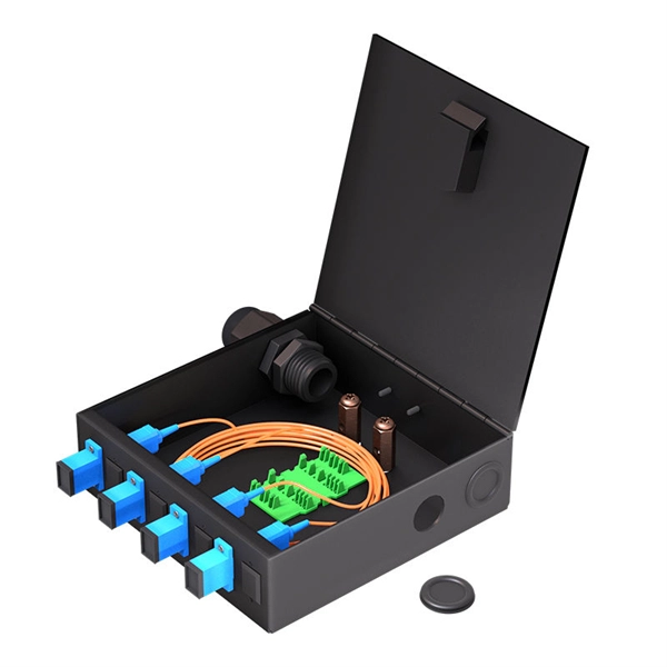
The function of a 10 Gigabit optical splitter
By dividing a single optical signal from a central Optical Line Terminal (OLT) into multiple outputs for Optical Network Terminals (ONTs) at users' homes, splitters eliminate the need for dedicated fibers to each residence—slashing infrastructure costs while scaling network reach. An Optical Splitter, also known as a beam splitter, is a passive optical device that divides a single input optical signal into two or more output signals. Conversely, it can also combine multiple signals into one. Optical splitter. Where splitters are placed in the network can make significant impacts on fiber counts, network cost and deployment time and operational steps, such as customer onboarding and maintenance. One important note is that splitting architectures should be seen as tools that can be mixed and matched to. The trick is how that single signal gets divided. That's where splitters come in.
[PDF Version]
-
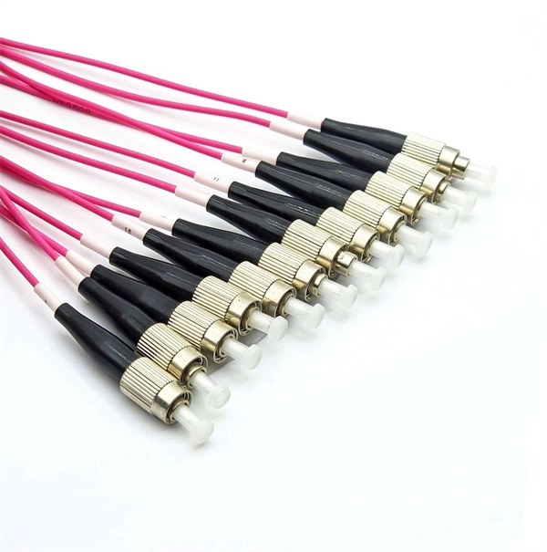
Working principle of 10 Gigabit fiber optic patch cord
The functioning of a fiber optic patch cord relies on its construction. It consists of a core with a high refractive index, enveloped by a coating featuring a lower refractive index. This assembly is fortified using aramid yarns and encased within a protective jacket. These cables, also known as fiber optic patch cables or jumpers, are designed to transmit information as pulses of light, offering unparalleled speed, bandwidth, and immunity to electromagnetic interference compared to traditional copper cables. As network demands continue to explode, selecting the. Key factors to consider in the design of 10 Gigabit Ethernet networks are: The network topology, including operating distances, splice losses and numbers of connectors (i. Fiber optic patch cables are found almost everywhere; cable television networks (CATV), data centers, computer networks, and telephone networks.
[PDF Version]
-
Kazakhstan Data Center Energy
Kazakhstan signed an agreement to build a $1. 5 billion Tier IV data center alongside a $400 million gas-fired power plant. The project is central to President Tokayev's ambition to transform Kazakhstan into a regional AI and digital infrastructure hub. Energy shortages, delayed power projects, and. Kazakhstan has signed a memorandum of cooperation with an international consortium that includes Dornan Engineering Group and JMOT04 to develop a major high-capacity data center project in the country. 5 billion investment, aiming to anchor its cognitive economy vision. Power supply challenge: A 250-megawatt gas plant is planned to ensure reliable electricity, with the country targeting energy self-sufficiency by 2027. There's one problem: the country doesn't currently have enough electricity to power what it already. Kazakhstan has announced a $1.
[PDF Version]
-
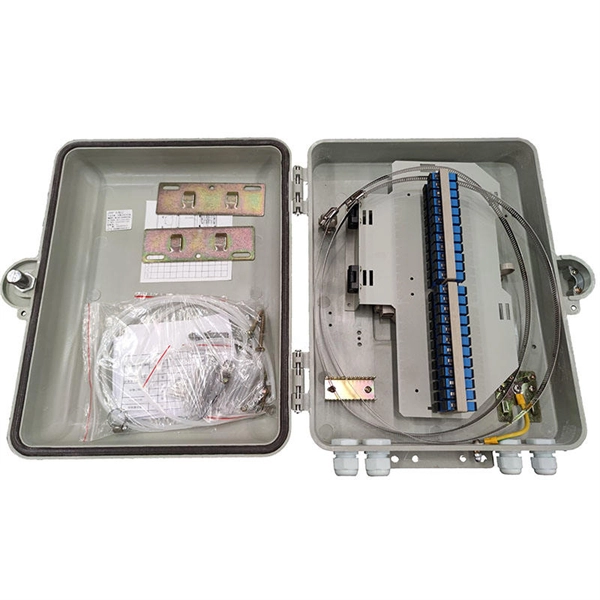
Center temperature of the distribution box
Target Temperature: Keep internal temperatures below 95°F (35°C) to ensure safe and efficient operation. Passive: Vents, shade, and natural airflow – best for mild conditions. Chances are it started with an overheated component in a distribution box somewhere upstream. Heat generation in electrical components follows Joule's first law – it's literally the energy tax we pay for moving electrons. The formula is simple: Heat = I²R. If it gets too hot, parts can stop working or even catch fire. In order to maximize the life cycles of your electronic devices and keep your business running, it is recommended to adequately control the temperature of your electrical components.
-

Configuration of circuit breakers for home data center distribution boxes
This guide shows you how to organize circuit breaker wiring properly. You will learn to build a safe, efficient, and professional electrical system today. Circuit breaker wiring configurations involve organizing main switches, busbars, and branch breakers within a distribution box. What Are Data Center Circuit Breakers? Data center circuit breakers are components of a data. Recommendations on how to select the correct circuit breakers and trip systems, best placement of circuit breakers in the PDUs and RPPS, and proper line and load Recommendations on how to select the correct circuit breakers and trip systems, best placement of circuit breakers in the PDUs and RPPS. Choosing the right size and setup for your distribution box keeps your electrical system safe and working well. Messy distribution boxes are dangerous and very hard to fix. Configuration: The switchgear is typically composed of multiple cubicles, including an incoming unit, outgoing unit, voltage metering unit, and bus section. Each cubicle is designed.
[PDF Version]