-
How many pigtails are there on a single optical fiber
A fiber pigtail is a single, short, usually, optical fiber that has an optical connector pre-installed on one end and a length of exposed fiber at the other end. The end of the pigtail is and to a single fiber of a multi-fiber trunk. Splicing of pigtails to each fiber in the trunk "breaks out" the multi-fiber cable into its component fibers for connection to the end equipment.
-
A single optical fiber uses a dual-core optical module
o In optical modules, "core" refers to the light-transmitting channel in the fiber. A 1-core module uses a single fiber core for data transmission, while a 2-core module uses two cores. They are easier to set up and give steady communication. A. Single fiber module also called BiDi transceiver or WDM module. BIDI module only has 1 port, wave filtering through the filter of module, and finished the transmitting of 1310nm optical signal. In today's communication field, single-core optical fibre and dual-core optical fibre are like remarkable stars, the powerful technology behind them and the disruptive impact on the communication industry deserve everyone's attention and discussion.
-
Cable and Optical Fiber Laying Methods
This comprehensive guide examines all major fiber installation methods, from underground trenching to submarine cable laying, providing technical insights drawn from industry best practices and real-world deployment experiences. We should always consider the restrictions established by different administrations related to this matter. Starting with site surveys and permissions, to installing fiber optic cable and emphasizing the process as a key stage in mastering fiber optic installation, to the careful handling of cables and high-stakes splicing, each stage is critical. Whether you're a technician, a network planner, or simply curious about fiber optic technology, this article will. This comprehensive guide explores the essential processes and best practices for underground fiber optic cable installation, helping business decision-makers understand the investment required to upgrade their telecommunications infrastructure.
[PDF Version]
-
How are 36 cores of power optical fiber cable divided
Multi-core optical fiber is a breakthrough in optical networking that packs multiple cores into one fiber, enabling tremendous capacity gains via spatial division multiplexing. By carrying parallel channels in a single strand, MCF allows operators to multiply bandwidth without. These optical signals are transmitted (Tx) and received (Rx) at deliberate power levels expressed and measured in milliwatts (mW), an absolute optical power level. Absolute levels may also be represented as a relative optical power level, known decibel milliwatt or dBm. Its primary function is to split the optical signal of one input optical fiber into multiple optical signals and transmit them to. MTP/MPO cables are a class of high-density multi-core fiber optic connectivity solutions widely used in data centers and telecom networks, which are designed to achieve fast connection of multi-core fiber optics through a single interface. In contrast to conventional single-core fibers (one core on the fiber axis), MCF can have two or more.
[PDF Version]
-

How to insert optical fiber into a collimator
Insert the fiber optic connector of the appropriate specification (matching the collimator interface, such as SC/FC) into the fiber optic interface of the collimator, gently rotate and tighten it to ensure a firm connection without looseness. Triplet Fiber Optic Collimators are high-precision collimating devices with an integrated triple-lens structure. They are primarily used to achieve efficient coupling between optical fibers and free-space optical paths, converting the divergent light beam emitted from the fiber into a highly. It is often necessary to transform the light output from an optical fiber into a free-space collimated beam. However, the fiber end has to be firmly fixed at a distance from the lens which is approximately equal. Thorlabs offers a variety of fiber collimation and coupling solutions. FiberPorts can be used to provide a stable platform for coupling light into and out of FC/PC, FC/APC, or SMA terminated fiber with five or six directional adjustments. In essence, a simple collimation lens is all that is needed for this purpose.
[PDF Version]
-

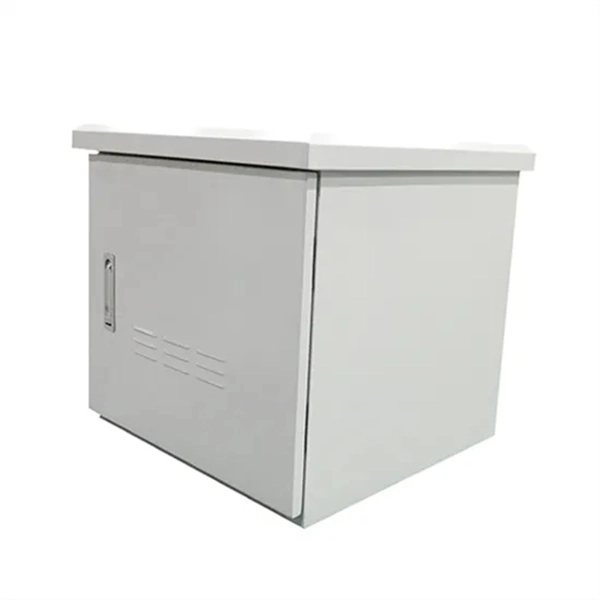
How to fix the optical cable in a Huijue fiber optic ODF box
Excavate the cable at the break point and use a fiber optic cutter to remove the damaged section. Use a high-precision fiber cleaver to prepare the fiber ends for. While a cut or damaged fiber optic cable can temporarily take your network down, it is possible to quickly fix the cable with the right tools. When fiber cables sustain damage, specialized repair techniques help restore connectivity and maintain data integrity. When it comes to ensuring nice network experiences for users, the condition of a fiber. As we move deeper into 2025, with global fiber deployments accelerating at a 10. Locates fiber breaks and measures signal loss before and after. Here are the steps to repair a cut fiber cable.
-

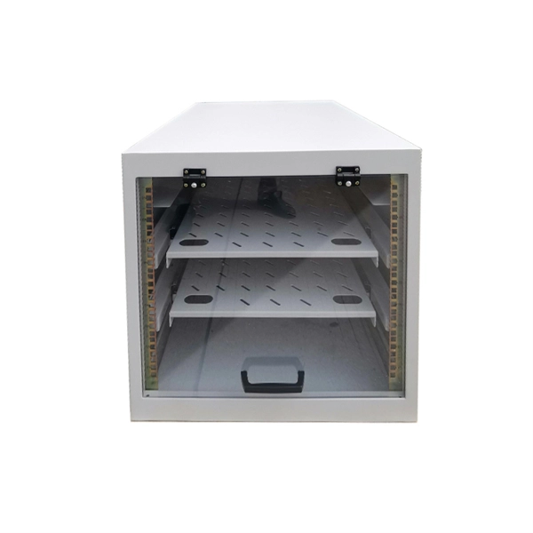
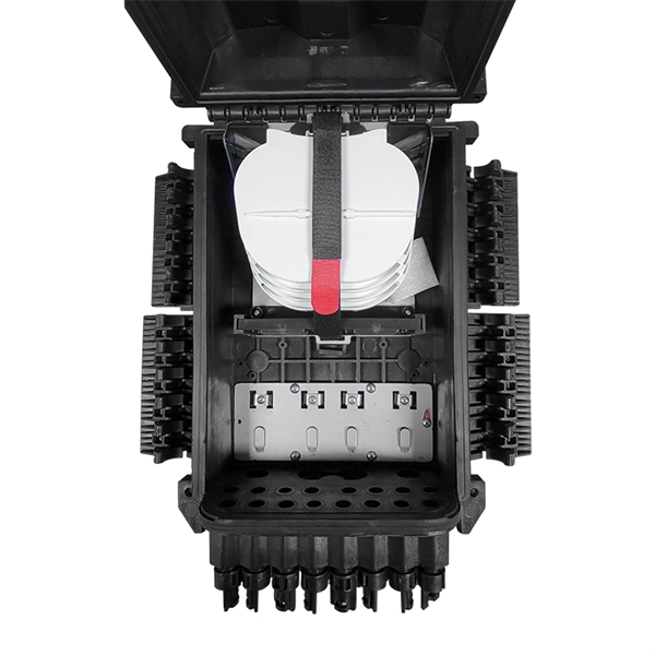
What is the fiber optic splice tray in the optical distribution box
• Splice Tray: This compartment is designed for fiber splicing and storage. It features slots or holders that secure spliced fibers, protecting them from bending, physical damage, or external stress. What is a Fiber Splice Tray Used for? With the increasing development of optical fiber networks, optical fiber terminals using fusion splicing or mechanical fusion have become common. Because optical fibers are sensitive to pulling, bending, and crushing forces, use fiber splice trays to provide. With the growth of FTTH, FTTx, and telecom fiber networks, the management of fiber optic splicing plays an increasingly important role in network reliability, performance, and maintainability. Inside splice closures, cabinets, and distribution frames, dozens or even hundreds of fibers need to be. Fiber Distribution Boxes (FDBs) are critical components in modern telecommunications infrastructure, particularly in fiber optic networks. Typically made from durable materials like plastic or.
[PDF Version]
-
How much optical loss does a fiber optic cold connector typically experience
Generally, for single-mode connectors, the recommended insertion loss is below 0. Insertion loss, also known as attenuation, is the loss of optical power that occurs when light passes through a fiber optic connector. It is caused by factors such as misalignment, air gaps, and imperfections in the connector components. This article explores various connector types—such as SC, LC, FC, ST, APC, and UPC—and analyzes how their design and polishing affect IL and RL performance. Insertion Loss (IL): Measures the. Fiber loss, also called fiber optic attenuation or attenuation loss, refers to the loss of signal between input and output.