-
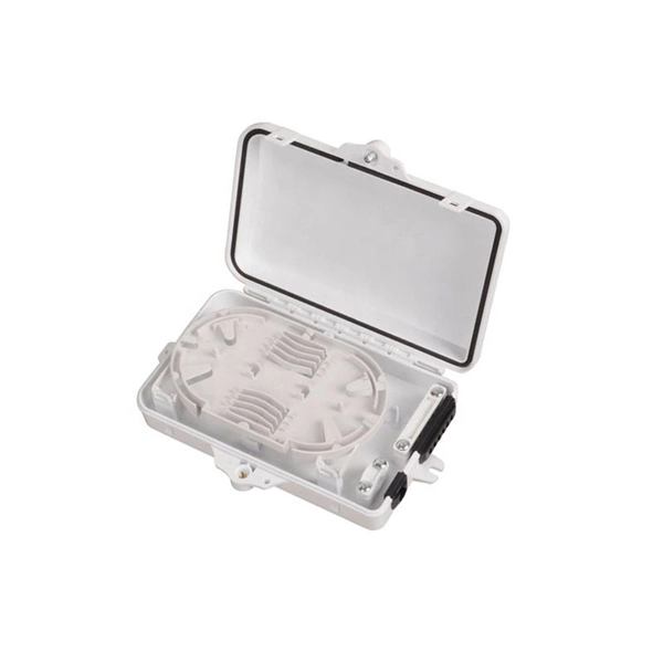
Should fiber optic cables or network cables be placed inside the cable tray
All cables should be supported in cable tray that is run overhead, above the equipment or under the raised floor. This paper addresses the routing of cable pathway beneath a raised floor to maintain optimal efficiency. Indoor cables can be installed in raceways, cable trays above ceilings or under. Question 1: Can mechanical utility piping or tubing containing water or compressed air be installed in cable trays with electrical cables? Answer: No. NEC section 300-8 does not permit. Indoor fiber cables should be placed in conduits or trays. cable installation must meet the NEC and local building code.
-
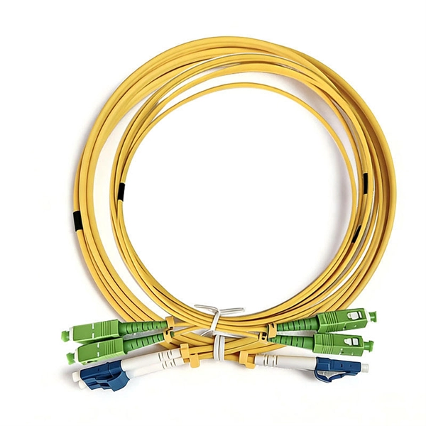
There are several fiber optic cable connectors inside the optical cable
The options on these cables dictate the fiber type, connector type, polarity, and polish type. The fiber types are SMF (Single-mode fiber) and MMF (multimode fiber). The fiber connector types, sometimes referred to as terminations, link fiber optic cables together through terminals, switches, adapters, and patch panels, by bridging the gap between their. While there are many different styles of connectors for single-fiber and multi-fiber cable assemblies, all basically share a similar construction. This article presents a brief overview of these key components. Fiber optic cables carry information between two places using entirely optical (light-based) technology. 5 µm wide, the alignment tolerance for any type of fiber. An optical fiber connector is a device used to link optical fibers, facilitating the efficient transmission of light signals.
[PDF Version]
-

How to use a cable locator to find optical cables
Cable locating equipment can help identify the exact location of buried fiber optic cables. Ground penetrating radar and electromagnetic field detection can help locate underground fiber. Fiber optic cables are critical components of modern communication infrastructure, often buried underground for protection and durability. However, locating these cables can be challenging without the right tools and knowledge. This guide will explain the most effective methods to locate buried. For locating purposes, the technician should first know if the fiber is armored with metallic shielding or unarmored without any type of metal built into the cable. Preparations before Locating III. When first introduced, it needed to do little more than find buried water, gas, or sewer lines. When you're digging or excavating on your private property, the last thing you want is to hit something important underground.
[PDF Version]
-

How to easily thread cables through cable trays
The main cable tray connection methods include splice plates, bolted connections, quick connect systems, fish plates, clamps, and welding. Choosing the right one depends on project conditions, load. In construction, electricity, telecommunications, and urban infrastructure projects, the cable pulling method plays a crucial role. more. Article Summary: A compliant cable tray installation requires a thorough understanding of NEC Article 392, proper structural support, and precise installation techniques. Wire mesh basket trays are an excellent option for a flexible and efficient cable management system. We want each and every experience with our.
-
Cables without armor are run in cable trays
The cables identified as Type TC-ER (Exposed Run) can be installed in industrial establishments for the connections between the cable trays and the equipment without metal conduits or armored cables Type MC (Metal Clad Cable); this kind of connections is called Open Wiring. Type TC – Tray Cable – (NEC Article 336) –Power and control tray cable type TC is a factory assembly of two or more insulated conductors, with or without associated bare or covered grounding conductors, under a non-metallic jacket. Pictured here are:. UL Listed shielded cables (THHN/THWN or TFN) built for the uses specified by art. 336 of ANSI/NFPA 70 “National Electrical Code” (NEC) and suitable for use in Class I, Division 2, Hazardous Locations. 8 meters (6 ft) of cable extends from the tray for a connection to a motor or other electrical device, cables without an ER rating must be either armored (type MC) or installed in conduit or another. Tray cable types TC, ITC and PLTC are permitted in cable trays by the NEC. CEC 12-904 (2) indicates that no raceway shall contain conductors of a different source unless they have metal armor.
[PDF Version]
-
Cables are run from the cable tray
A cable tray is an organized support structure designed to secure and route these insulated electrical cables. It acts as a dedicated pathway for power distribution and data transmission, often supporting cables hidden behind walls or above ceilings. Cable tray is the preferred wiring method for industrial facilities, data centers, and large commercial buildings where routing dozens or. The two most common methods to transition from a cable tray to the equipment are: Cables or conductors leaving the cable tray and entering the equipment through a raceway with a bushing on the end (see image A). There are many different types of cable tray including basket, ladder and solid-bottom.
-
Degradation factor for cables laid in cable trays
Based on the standard table, the grouping factor would be approximately 0. 39 — meaning every cable must be derated to 39% of its tabulated rating. 54. The Current rating of power cables is defined by the maximum intensity of current (amperes) which can flow continuously through the cable, under permanent loading conditions, without any risk of damaging the cable or deterioration or its electrical properties. Unlike cables installed in open air or conduit, cables placed in cable trays experience different heat. conductor 600 V and 5 KV cables #4 AWG and larger are routed in power trays in a single layer with 3/8" minimum spacing between cables. Cable ampacities, showTI below, are obtained from ICEA. Scenario: A cable tray in an industrial MCC room carries 18 multicore cables. Present method of utilizing derating factors from IEC 60364-5-52 for sizing cables in ladde trays is overtly conservative and assumes that all cables are fully loaded. The derating factor is a multiplier used to reduce the nominal current rating of a cable.
[PDF Version]