-
Principle of Fiber Optic Communication Spectrum Analyzer
These instruments are used to measure wavelength emissions from Lasers, Laser Diodes and LED's into the near infrared. From detecting signal distortions to optimizing optical. Optical spectrum analyzers are specialized instruments that measure light intensity as a function of wavelength. The COSA-4055 module offers the functionality and speed of an OSA in a handheld form factor at a fraction of. E/O converters use light-emitting elements such as semiconductor lasers, O/E converters use light-receiving elements such as photodiodes, and optical elements such as lenses are used at the input and output of optical fiber.
-

Spectrum Analyzer Intensity
An optical spectrum analyzer uses reflective or refractive techniques to separate out the wavelengths of light. An electro-optical detector is used to measure the intensity of the light, which is then normally displayed on a screen in a similar manner to a radio- or audio-frequency spectrum analyzer. The input to an optical spectrum analyzer may be simply via an aperture in the instrument's case, an. OverviewA spectrum analyzer measures the magnitude of an input signal versus frequency within the full frequency range of the instrument. The primary use is to measure the power of the spectrum of known and. analysis was first used by in the late 1600s. In a letter to the, he described how he used an optical prism to separate white light into its constituent colors. Spectrum a. Spectrum analyzer types are distinguished by the methods used to obtain the spectrum of a signal. There are swept-tuned and fast Fourier transform (FFT) based spectrum analyzers: • A.
[PDF Version]
-
Underground Depth of Optical Cable
Fiber optic cables are typically buried between 12 and 36 inches (30–90 cm), depending on installation environment, soil conditions, and load requirements. In high-load areas such as roads or backbone routes, burial depth can reach 48 inches (120 cm) or more. With international fiber networks predicted to grow to over 1. 8 million km in scope by 2025 (per TeleGeography), burying these cords of light comes with the benefits of avoiding cable damage, decreasing downtime, and extending their operational lifetime. For broader context on underground. Underground cables are pulled in conduit that is buried underground, usually 1-1. 2 meters (3-4 feet) deep to reduce the likelihood of accidentally being dug up. In extreme cold climates, cables may need to be buried at greater depths where there temperatures are colder and frost penetrates to. Estimate minimum burial depth (cover) for underground electrical, fiber, and low-voltage cable runs using a practical, code-aware ruleset. Always consult local utility regulations and obtain necessary permits before excavation.
[PDF Version]
-

Benin Optical Cable Blowing Machine
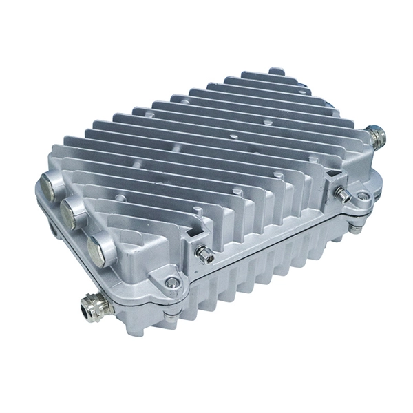
A cable blowing machine (also known as a fiber blowing machine) is a machine designed to fit cables into telecommunication ducts and with the use of compressed air or water.
-
North Macedonia Optical Line Terminal 10G
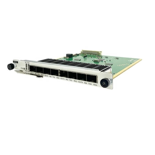
The 10G SFP+ LR Ethernet Line optical transceiver transmits data over single mode fibre at a distance of up to 10km. The transceiver operates on 1 wavelength and works in point-to-point scenario. Modern OLTs offer communication service providers (CSP) the ability to launch multigigabit services to tens of thousands of subscribers from a single location or just ten. Fiber-to-the-home. HA7308VX is a small capacity 8 port OLT device launched by HiOSO. It can be used with HA7200 series ONU and passive optical distribution network (ODN) to form a passive optical network to achieve performance management, fault management, and configuration management of the equipment. 5G/5G/10GBase-T Multi-rate SFP+ Module (Twisted Pair Category Cable, 100m 1G/2. 5G Cat5e, 70m 5G Cat5e, 30m 10G Cat6a/7, RJ-45, C-temp) Specifications Form. Field-proven EPON and 10G-EPON OLT SoC solutions Cortina family of Optical Line Terminal (OLT) SoCs completes the end-to-end solutions for EPON and 10G-EPON applications.
[PDF Version]
-
10 Gigabit Ethernet card optical module not connected to fiber optic cable
Troubleshooting SFP+ link issues in 10 GbE networks requires attention to module type, match of speed and wavelength, clean fiber connections, correct configuration, thermal management, and equipment compatibility. You can quickly resolve SFP+ Module connectivity issues by following a systematic optical transceivers troubleshooting process. Check for common connection problems, such as link failures or modules not recognized. Check compatibility between the optical module and switch Most switch brands have specific compatibility requirements. During network upgrades, many enterprise users encounter a common issue: after replacing 10G broadband lines or inserting 10G SFP+ optical modules, the switch still fails to operate at full 10G bandwidth or even fails to recognize the modules. We've listed the five most common ones. First of all, let's briefly recap what SFP and SFP+ stand for. SFPs – short for 'small form-factor pluggable' – are compact, hot-pluggable devices.
[PDF Version]
-
Which port on the switch is the optical interface
The optical port of an industrial Ethernet switch refers to the optical fiber interface, which has single-mode, multi-mode, gigabit, and gigabit specifications. Port types are limited to two: optical and Ethernet. RJ45 ports serve access-layer copper connections; SFP/SFP+ ports enable flexible 1G/10G uplinks; SFP28 delivers 25G for modern data centers; QSFP+ and QSFP28 support high-density 40G/100G spine–leaf. GBIC is an interface device that converts gigabit electrical signals into optical signals. This design enables end-to-end optical signal transmission, avoiding the conversion between electrical and. The optical ports on the switch are usually paired together, with one TX sender and one RX receiver. The. Most SFP fiber optic modules use LC connectors, while SC connectors are mainly found in legacy networks and MPO/MTP connectors are used for high-density cabling rather than directly on standard SFP modules. This connector landscape reflects how modern SFP deployments prioritize port density and.
[PDF Version]
-
Switches are all 10 Gigabit optical
To implement different 10GbE physical layer standards, many interfaces consist of a standard socket into which different physical (PHY) layer modules may be plugged. PHY modules are not specified in an official standards body but by (MSAs) that can be negotiated more quickly. Relevant MSAs for 10GbE include (and related X2 and XPAK), and. When choosing a PHY.