-
Optical Cable Line Engineering Construction and Maintenance
These services include engineering and design, placement of aerial and underground optical fiber cable and coaxial construction, optical fiber cable splicing and testing, maintenance, installation and emergency restoration. Optical Fiber Cable Engineering Construction: A Comprehensive Operation Guide 1. Introduction Optical Fiber Cable engineering construction refers to the process of designing, planning, executing, and maintaining communication system infrastructure by deploying optical cables and associated. DeployCom is a premier provider of broadband design, engineering, construction and network installation for fiber optic cable services. Additionally, DeployCom provides project management, maintenance and disaster recovery services for broadband network projects. We approach each client's needs. The Fiber Optic Association, Inc. (FOA) was founded in 1995 to help develop the workforce to build the fiber optic networks to support a rapid expansion in communications and the Internet.
[PDF Version]
-
CAD Engineering Cable Tray Filling
Download a comprehensive set of Cable Tray Installation CAD Blocks in DWG format, ideal for electrical engineers, MEP designers, and industrial layout planners. In the Electrical workspace, click Home tabBuild panel. The cable tray and conduit tools have specific. Paneldes Raceway is the 3D CAD design module of EDS used for the creation of Plant Raceway models. Paneldes software performs cable routing, cable filling and cable length calculations, as well as interference analysis and materials reporting. Paneldes Raceway software is for construction engineers. Discover all CAD files of the "Cable trays" category from Supplier-Certified Catalogs ✅ SOLIDWORKS, Inventor, Creo, CATIA, Solid Edge, autoCAD, Revit and many more CAD software but also as STEP, STL, IGES, STL, DWG, DXF and more neutral CAD formats.
-

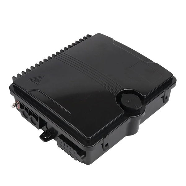
Installation of Optical Distribution Box in Telecommunications Engineering
This guide provides a comprehensive engineering perspective on ODFs—beyond the basic “what is an ODF” explanation—covering structural design, fiber management, MPO/MTP integration, and selection criteria for modern high-density deployments. Why ODFs are the Foundation. Fiber optic technology has revolutionized the telecommunications industry, enabling faster and more reliable data transmission. In this article, we will delve into the world of fiber optic distribution boxes -. technical specialist at Spring Optical, focusing on Data Center cabling Solution, FTTA Solution, FTTH Solution, and ODN Solution for global telecom, ISP, and data center network deployments. A fiber optic wall plate is a critical indoor FTTH termination component that connects fiber drop cables to. This instruction describes the installation of the Fiber Distribution Frame (FDF) manufactured by Corning Optical Communications. It can also be deployed in any cross-connect architecture and still provide clear, managed pathways for fiber. Determine the installation position: - Determine the installation position of the optical fiber distribution box based on the.
[PDF Version]
-

How to install the cable tray beam bend
The fittings can fastened to the cable tray rail either with double clamps of type DOP A2 or with truss-head bolts of type FRS and combination nuts. The exceptions to this are vertical bends, adjustable bend elements and fittings with a side height of 35 mm. These fittings can only be screwed on. Beam bracket PK1 is attached to the lower flange of an I beam. These guidelines are not intended to cover all details or variations in cable ladder and cable tray. en completely installed, without damage either to conductors or structural system use maintain spacing or to keep cables in place when the tray is ect the minimum bend ra-dius for cables as they exit the bottom of the cable tray. A rung spacing of 6 to 9 inches (150 to 230 mm) is preferable when. Hubbell's NEXTFRAME® Ladder Tray is the effective and widely used cable runway that supports and delivers bundles of cable between cabinets, racks, and closets, along walls, and suspended from ceilings. Cable ladder systems and cable tray systems shall be manufactured in accordance with BS EN 61537, channel support.
[PDF Version]
-

How to bend a cable tray gqi
You can buy a manufactured 90 degree bend or make one on a cable tray bending machine but in this video I show you how to make one using a metal bar. Students trading aid on how best to put an internal 90 degrees bend in steel cable tray. By following these steps, you can minimize the risk of damage to the cable tray and ensure a smooth bending experience. When a wire cable tray is cut, the fact that a. I am an apprentice electrician and looking knowledge on how to create a 90° bend on a cable tray suitable for SWA.
-

Bending angle of vertical bend in cable tray
A box type cable tray vertical outside bend is a fitting used to change the direction of a cable tray system vertically, typically at a 90-degree angle, directing cables outward. How to calculate cable tray bends? Calculate the minimum required bend radius by multiplying the cable's outside diameter by its bending factor (e. Then, select a standard tray fitting (300mm, 450mm, etc. ) that matches or exceeds this value. Use this tool to estimate sloped section length, horizontal run requirement, cut marks, and installation feasibility. Measure this distance along the straight tray. 90° bend, Vertical Inner Bend, for all cable tray types of 50 mm side height. How to bend 90 degree of cable tray 3 line with the same distance :// • HOW TO BEND 90 DEGREE OF CABLE TRAY 3 LINE.
-
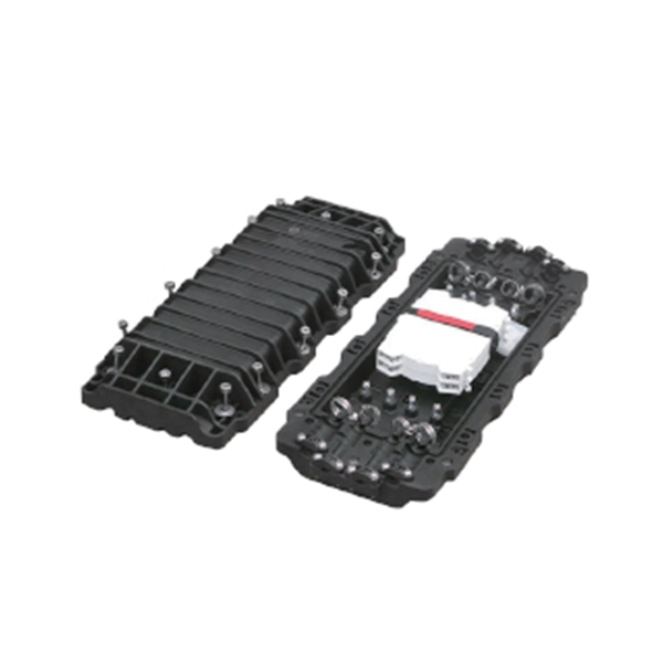
What is a horizontal optical cable junction box called
Fiber Cable Joint Box is a device used to provide space and protection for fiber optic cables spliced together. Optical cable splice boxes protect the splicing parts of optical fibers from various hazards, such as water seepage due to adverse. A Fiber Terminal Box (FTB) is a customer-side termination and distribution device used at the end of the optical network. ■ What Is a Fiber. Fiber optic splice closures are essential components in today's communication networks. These closures protect and organize splicingfiber connections, ensuring the integrity of opticalsignal transmission.