-
One fiber optic cable core is broken
This guide provides a detailed roadmap for locating and fixing fiber optic cable breaks, covering detection techniques, repair methods, and best practices. Accidental cuts, breaks, or other damage can disrupt your network and cause costly downtime. With the right tools and techniques, you can efficiently repair damaged fiber cables and restore. In today's hyper-connected world, fiber optic cables serve as the lifelines of high-speed data transmission, powering everything from global telecom networks to local FTTH (Fiber to the Home) systems. However, a break in these delicate glass strands—whether from construction mishaps, environmental. Fiber optic cables are typically damaged in one of two ways: A premade fiber optic cable suffers connector damage when too much pull-force is applied during installation. This can occur on long cable runs through tight conduit or duct, and also if the cable becomes caught or snagged. A fiber optic. These cables consist of a core (glass or plastic) that carries light signals, surrounded by cladding to reflect light inward, a buffer for protection, and an outer jacket for durability.
[PDF Version]
-
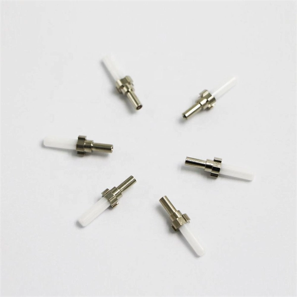
What is a fiber optic cable fused core
Fiber Fusing is a mechanism used to protect fiber optic cables from damage caused by unsafe levels of optical power. This. A fiber optic cable consists of five basic components: the core, the cladding, the coating, the strengthening fibers, and the cable jacket. When searching for a fiber optic cable, we need to pay attention not only to the connectors, such as SC to ST fiber cable, LC to SC fiber patch cable, or SC to. This page explains the basics of a fiber fuse and its function within a fiber optic network. We're all familiar with fuses used in electrical devices, right? A fuse is a safety device that interrupts the flow of current when an electrical circuit is overloaded., at the output end), propagates back towards the light source, melting and destroying the fiber core along its path. Professionals in telecommunications, data centers, and network infrastructure must understand the core functions and why they are fundamental to their fiber optic. However, if there were no cores, fiber optic cables would be useless.
[PDF Version]
-
How much does it cost to lay one meter of 24-core fiber optic cable
In practical terms, the current market range for a standard single-mode 24 core fiber optic cable typically falls between $1. Fiber-optic cable materials typically cost $1 to $6 per linear foot, depending on fiber count and cable type. Commercial building installations with 100-200 network drops generally range from $15,000 to $30,000. Main cost drivers include cable grade (indoor vs outdoor, armoured), distance, and labor for trenching, splicing, and termination. This guide presents ranges in USD and practical price estimates to help. Buyers typically pay for fiber laying by combining material costs, labor time, and permitting plus trenching or aerial support fees. Labor dominates the installed price. Understanding cost ranges helps buyers budget.
-
What to do if the fiber optic cable fusion splice core is misaligned
Check the fusion splicer's alignment system and settings. The root causes typically include: To resolve this, first check the fibre ends. Spending a few extra minutes on calibration often saves significantly more time by preventing failed splices and rework. It is also important to regularly check: These. Place the fibers carefully into the V-grooves of the splicer while aligning the fiber cores along the centerlines so as not to induce splice loss from misalignment of the fiber cores. Ensure proper fibre cleaving techniques, using a high-quality fibre cleaver and following manufacturer guidelines. IEC 61300 standards and best practices from Corning and 3M guide professionals toward consistent performance.
-
Horizontal deviation of each meter of horizontal cable tray
Horizontal deviation: ≤2mm per meter. Must be level, plumb, and securely mounted on supports. Calculate horizontal, vertical, or compound cable tray offsets based on bend angle, offset distance, and available installation space. Use dedicated splice plates and. The maximum horizontal distance shall be 76-meters (250 ft). For ease of cable installation and future expansion in hallway or major distribution routes, cable trays are the preferred method for distributing the horizontal wiring from the telecommunications room to the communication outlets. When. NEMA Standards Publication VE 2-2018 Cable Tray Installation Guidelines Endorsed by Cable Tray Institute www. com Published by: National Electrical Manufacturers Association 1300 North 17th Street, Suite 900 Rosslyn, Virginia 22209 www. This spacing should generally be no less than 0. The primary reason for this separation is to minimize electromagnetic interference (EMI), which could.
[PDF Version]
-

Composition of butterfly-shaped drop fiber optic cable
FTTH Butterfly Optic Cables, also known as flat drop fiber cables, feature a compact flat profile with optical fibers placed at the center and reinforced by parallel strength members on both sides. Then, the cable is completed with LSZH sheath. Also, customers can specify your required connectors. Environmental Performance. Abalone Tech's 1/2/4F Self-supporting Butterfly Drop Cable is designed for aerial and duct installations in FTTH (Fiber-to-the-Home) and telecom networks. 5 kg/km Optical Performance: Insertion loss <0.
-
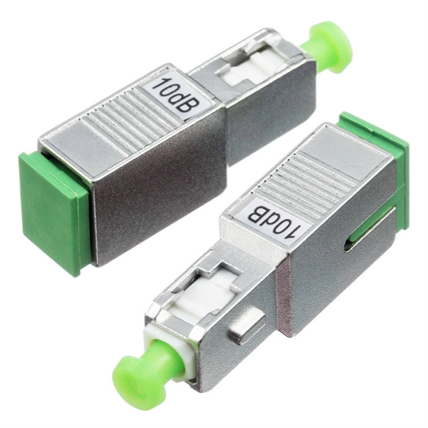
Fiber optic cable connected to router then connected to switch
If using a network switch with SFP ports, insert the fiber optic transceiver into the SFP port and connect the fiber optic cable to the transceiver. Connect the other end of the Ethernet cable to your network device, such as a computer, router, or. Fiber Optic Transceiver: Often used with media converters or network switches, these devices convert electrical signals to optical signals and vice versa. Patch Panel. As we speak I just have optic fibre (Community Fibre) connected to my Huawei modem / Linksys Velop which will be connected to a new POE switch (need to identify the best model to be compatible with my optic fibre extension project). Network topology refers to the way in which the links and nodes of a network are arranged in relation to each other. Use a standard Ethernet cable (Cat5e/Cat6) to.
[PDF Version]
-
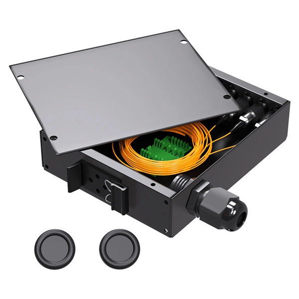
Fiber optic cable outer sheath representation
1 The outer cable jacket shall be marked with the manufacturer's name, date of manufacture, fiber count, fiber type, flame rating, listing symbol, and sequential length markings every two feet (e., “CORNING OPTICAL COMMUNICATIONS OPTICAL CABLE - MM/YY. XXXXX (feet. One important consideration when selecting indoor fiber optic cables is the outer sheath material and its fire prevention level. Each cable is single packed in a polybag with a test report that guarantees best performance in typical application scenarios like telecommunication, rack cabling, sensor technologies or indust Choosing the appropriate outer sheath material for fiber optic cables is crucial for ensuring the cable's durability, protection, and performance under specific environmental conditions. At the same time, it must have. 1. 1 The cable shall meet all requirements stated in this specification. Glass fiber and plastic fiber is fragile.
[PDF Version]
-
Requirements for installing cable trays on highways
Cable tray systems are recognized as a wiring method by many national and international electrical codes. Typical requirements address: Tray construction, load ratings, and materials. Support spacing, mechanical strength, and. Article Summary: A compliant cable tray installation requires a thorough understanding of NEC Article 392, proper structural support, and precise installation techniques. This guide covers the critical steps, from selecting the right electrical cable tray and performing accurate cable fill. This article explains the main requirements and good practices for cable tray systems, including tray types, materials, loading, supports, bonding, cable selection, and installation details.
-

Benin Optical Cable Blowing Machine
A cable blowing machine (also known as a fiber blowing machine) is a machine designed to fit cables into telecommunication ducts and with the use of compressed air or water.
-
Underground Depth of Optical Cable
Fiber optic cables are typically buried between 12 and 36 inches (30–90 cm), depending on installation environment, soil conditions, and load requirements. In high-load areas such as roads or backbone routes, burial depth can reach 48 inches (120 cm) or more. With international fiber networks predicted to grow to over 1. 8 million km in scope by 2025 (per TeleGeography), burying these cords of light comes with the benefits of avoiding cable damage, decreasing downtime, and extending their operational lifetime. For broader context on underground. Underground cables are pulled in conduit that is buried underground, usually 1-1. 2 meters (3-4 feet) deep to reduce the likelihood of accidentally being dug up. In extreme cold climates, cables may need to be buried at greater depths where there temperatures are colder and frost penetrates to. Estimate minimum burial depth (cover) for underground electrical, fiber, and low-voltage cable runs using a practical, code-aware ruleset. Always consult local utility regulations and obtain necessary permits before excavation.
[PDF Version]
-
Cables without armor are run in cable trays
The cables identified as Type TC-ER (Exposed Run) can be installed in industrial establishments for the connections between the cable trays and the equipment without metal conduits or armored cables Type MC (Metal Clad Cable); this kind of connections is called Open Wiring. Type TC – Tray Cable – (NEC Article 336) –Power and control tray cable type TC is a factory assembly of two or more insulated conductors, with or without associated bare or covered grounding conductors, under a non-metallic jacket. Pictured here are:. UL Listed shielded cables (THHN/THWN or TFN) built for the uses specified by art. 336 of ANSI/NFPA 70 “National Electrical Code” (NEC) and suitable for use in Class I, Division 2, Hazardous Locations. 8 meters (6 ft) of cable extends from the tray for a connection to a motor or other electrical device, cables without an ER rating must be either armored (type MC) or installed in conduit or another. Tray cable types TC, ITC and PLTC are permitted in cable trays by the NEC. CEC 12-904 (2) indicates that no raceway shall contain conductors of a different source unless they have metal armor.
[PDF Version]